
Adaptive power management in imaging systems

a power management and imaging system technology, applied in the field of adaptive power management in imaging systems, can solve problems such as power waste, and achieve the effects of reducing power consumption, wasting power, and reducing electrical power consumption

Active Publication Date: 2010-04-29
SYMBOL TECH LLC
View PDF4 Cites 24 Cited by
  • Summary
  • Abstract
  • Description
  • Claims
  • Application Information

AI Technical Summary

Benefits of technology

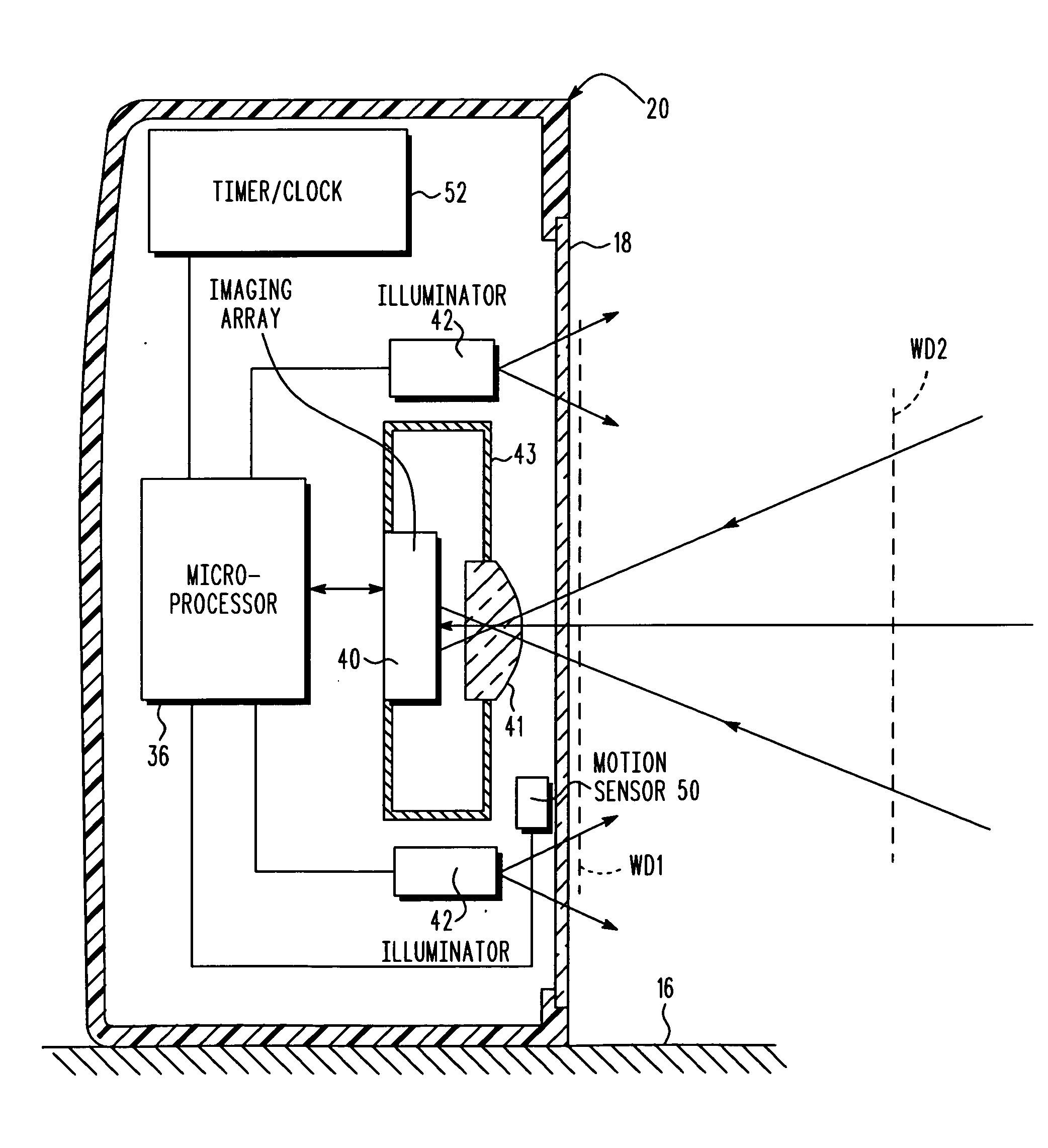
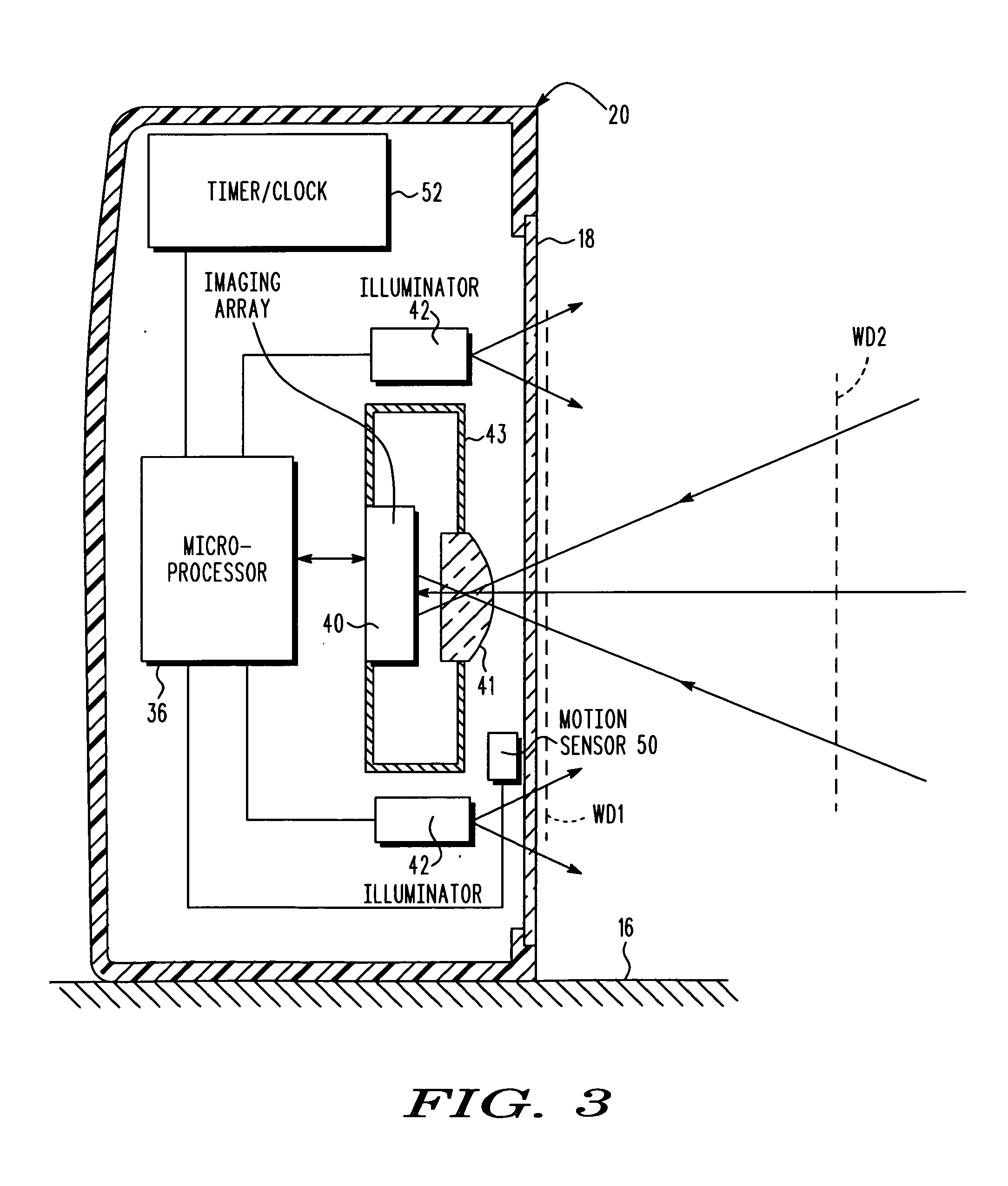
[0012]In accordance with the present invention, a power reducer is operatively connected to the controller, for adaptively reducing electrical power consumption of at least one of the illuminator and the controller, as well as preferably other electrical components of the system, based on system usage. In one embodiment, the power reducer is a manually actuated switch operatively connected to the controller, for operating the system in a sleep mode in which the controller deenergizes, either fully or partially, at least one of the illuminator and the controller, if not both, when the switch is manually actuated. In the event that a trigger is provided on the housing, then it is advantageous if the manually actuated switch for reducing power is the trigger. The trigger is normally manually actuated for a reading time period, for example, one second or less, to initiate an active reading mode. To use the trigger as the switch for reducing power, the trigger is manually actuated for a shutdown time period, for example, three seconds, which is longer than the reading time period to initiate the sleep mode. This helps alleviate the prior art problem of having the illuminator flash for a long time period, thereby wasting power.
[0013]In another embodiment, the power reducer is a timer, a motion sensors or a program for operating the controller to periodically adjustably deenergize, either fully or partially, at least one of the illuminator and the controller, if not both, as well as preferably other electrical components of the system, in an idle mode in which the system is inactive, at a variable frequency that decreases over time. For example, the controller can be preprogrammed to adjustably set the frequency at the beginning of the idle mode at a relatively high value, such as 100 milliseconds, and then the controller after continued inactivity can gradually reduce the frequency to a relatively lower value, such as 10 seconds or more. This helps alleviate the prior art problem of having the illuminator flash at the same frequency.
[0014]In still another embodiment, the power reducer is a timer for measuring inactive time periods between reading the targets, and for operating the controller to periodically adjustably deenergize, either fully or partially, at least one of the illuminator and the controller, if not both, as well as preferably other electrical components of the system, in an idle mode in which the system is inactive at a frequency that depends upon the measured inactive time periods. If the measured inactive time periods are short, then the frequency can be adjustably set at a higher rate. If the measured inactive time periods are long, then the frequency call be adjustably set at a lower rate. This helps alleviate the prior art problem of having the illuminator flash at the same frequency.

Problems solved by technology

This helps alleviate the prior art problem of having the illuminator flash for a long time period, thereby wasting power.

Method used


Image

  • Adaptive power management in imaging systems
  • Adaptive power management in imaging systems
  • Adaptive power management in imaging systems

Examples


Embodiment Construction

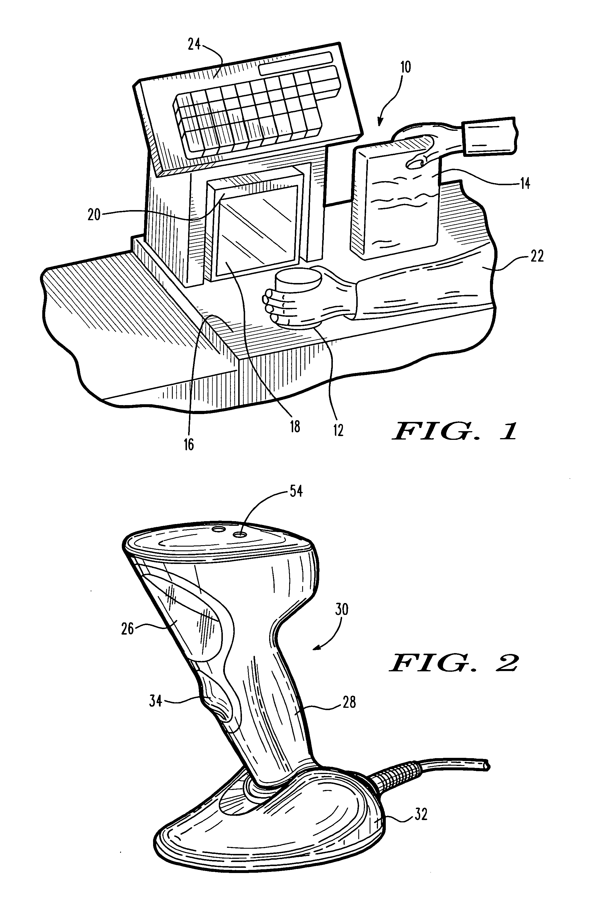
[0024]Reference numeral 10 in FIG. 1 generally identifies a workstation for processing transactions and specifically a checkout counter at a retail site at which products, such as a can 12 or a box 14, each bearing a target symbol, are processed for purchase. The counter includes a countertop 16 across which the products are slid at a swipe speed past, or presented to, a generally vertical or upright planar window 18 of a portable, box-shaped, vertical slot reader or imaging system 20 mounted on the countertop 16. A checkout clerk or operator 22 is located at one side of the countertop, and the imaging system 20 is located at the opposite side. A host or cash / credit register 24 is located within easy reach of the operator. The operator 22 can also hold the imaging system 20 in one's hand during imaging.

[0025]Reference numeral 30 in FIG. 2 generally identifies another imaging system having a different configuration from that of imaging system 20. Imaging system 30 also has a generall...


PUM


Abstract

An imaging system for, and a method of, electro-optically reading targets, utilize an energizable illuminator for illuminating an illuminated target with illumination light, a solid-state, energizable imager having an array of image sensors for capturing return light from the illuminated target over a field of view, and for generating electrical signals indicative of the captured return light, and a controller for energizing the illuminator and the imager to process the electrical signals into data indicative of the illuminated target. A power reducer is operatively connected to the controller, for adaptively reducing electrical power consumption of the illuminator and / or the controller based on system usage.

Description

DESCRIPTION OF THE RELATED ART[0001]Solid-state imaging systems, in both handheld and hands-free active reading modes of operation, have been used in supermarkets, warehouse clubs, department stores, and other kinds of retailers for many years, to electro-optically read targets, such as one-dimensional bar code symbols, particularly of the Universal Product Code (UPC) type, each having a row of bars and spaces spaced apart along one direction, and two-dimensional symbols, such as Code 39, which introduced the concept of vertically stacking a plurality of rows of bar and space patterns in a single symbol, as described in U.S. Pat. No. 4,794,239. Another two-dimensional code structure for increasing the amount of data that can be represented or stored on a given amount of surface area is known as PDF417 and is described in U.S. Pat. No. 5,304,786.[0002]The solid-state imaging system has also been used to capture images or pictures of a non-symbol target, and include an imager having a...

Claims


Application Information

Patent Timeline
Patent Type & Authority Applications(United States)
IPC IPC(8): G06K7/10
CPCG06K7/10G06K7/10861G06K7/10851
Inventor MADEJ, DARIUSZ J.VINOGRADOV, IGOR
Owner SYMBOL TECH LLC
Learn More