
Injection molding method for making large and thin light guide plate

a technology of injection molding and light guide plate, which is applied in the field of injection molding, can solve the problems of difficult to ensure the quality of such large and thin light guide pla

Inactive Publication Date: 2010-04-29
HON HAI PRECISION IND CO LTD
View PDF2 Cites 2 Cited by
  • Summary
  • Abstract
  • Description
  • Claims
  • Application Information

AI Technical Summary

Benefits of technology

The present invention provides an injection molding method for making large and thin light guide plates, which are commonly used in electronic devices such as mobile phones and laptop computers. The method can overcome the challenges of making such plates, such as porosity and shrinkage, by using a specific mold apparatus and injecting a molding material into the mold at a high pressure and velocity. The resulting light guide plates are of high quality and can be used in thin laptop computers.

Problems solved by technology

However, because of the size of the light guide plates, defects such as porosity and shrinkage are likely to occur during the injection molding process, thus it is difficult to ensure quality of such large and thin light guide plates.

Method used


Image

  • Injection molding method for making large and thin light guide plate
  • Injection molding method for making large and thin light guide plate
  • Injection molding method for making large and thin light guide plate

Examples


Embodiment Construction

[0013]Embodiments of the present method will now be described in detail below with reference to the drawings.

[0014]Referring to FIGS. 1 to 5, an exemplary injection molding method 100 for making a large and thin light guide plate 60, is provided. A length of the light guide plate 60 is in a range from 30 to 50 centimeters, a width of the light guide plate 60 is in a range from 20 to 35 centimeters, and a thickness of the light guide plate 60 is in a range from 0.4 to 0.8 millimeters. The method mainly includes the steps as follows.

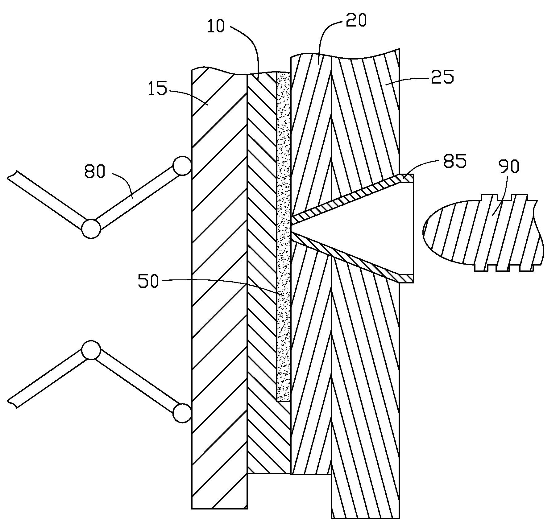
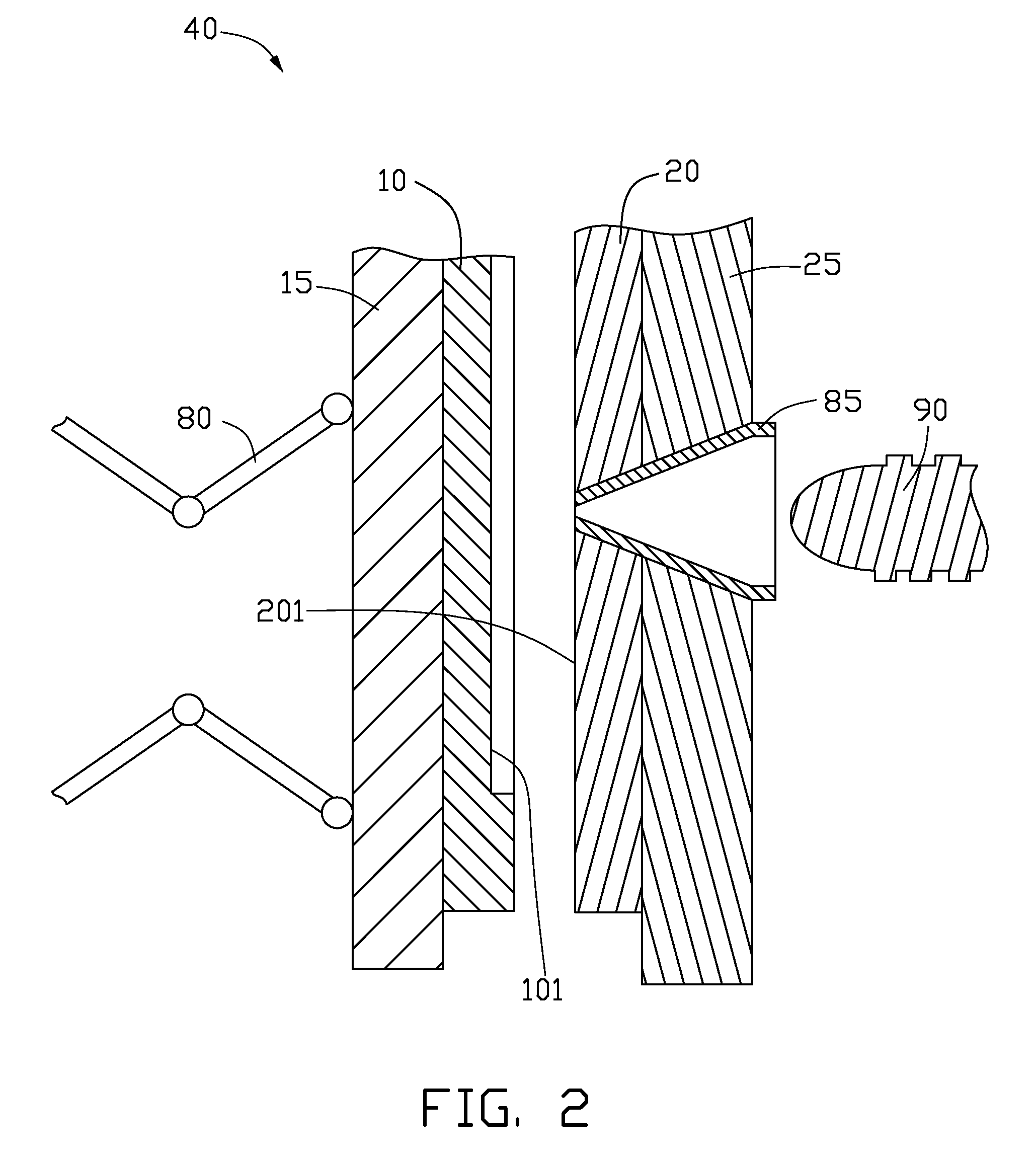
[0015]First, a mold apparatus 40 is provided. The mold apparatus 40 includes a first mold 10, a second mold 20, a first clamping plate 15, a second clamping plate 25, a toggle mechanism 80, a sprue 85, and a screw 90. The first mold 10 is mounted to the first clamping plate 15, and the toggle mechanism 80 is mounted to the first clamping plate 15. The second mold 20 is mounted to the second clamping plate 25, and the sprue 85 is mounted to the second clamp...


PUM

PropertyMeasurementUnit
clamping forceaaaaaaaaaa
thicknessaaaaaaaaaa
widthaaaaaaaaaa

Abstract

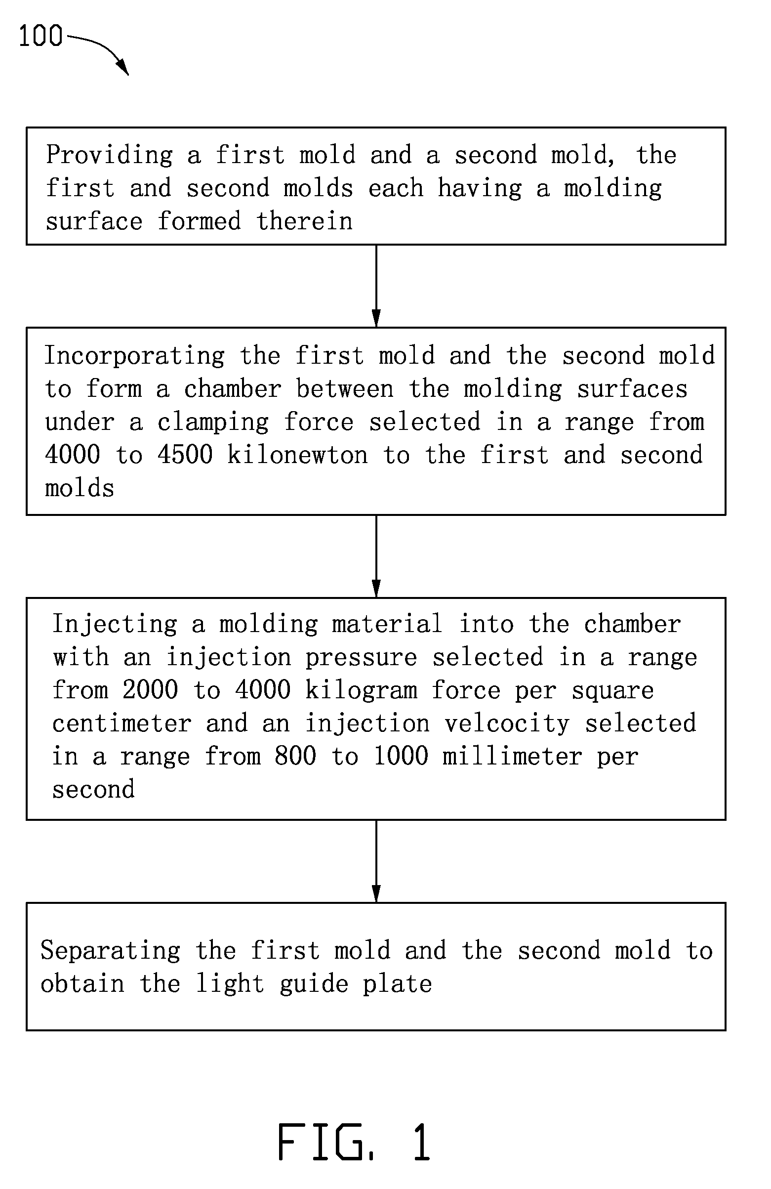
An injection molding method for making a large and thin light guide plate, is provided. First, a first mold and a second mold are provided. The first and second molds each have a molding surface formed thereon. Second, the first mold and the second mold are incorporated together to define a chamber between the molding surfaces under a clamping force selected in a range from 4000 to 4500 kilonewton to the first and second molds. Third, inject a molding material into the chamber with an injection pressure selected in a range from 2000 to 4000 kilogram force per square centimeter and an injection velocity selected in a range from 800 to 1000 millimeter per second. Finally, the first mold and the second mold are separated to obtain the light guide plate.

Description

BACKGROUND[0001]1. Technical Field[0002]The present invention relates to injection molding, and particular, to an injection molding method for making a large and thin light guide plate.[0003]2. Description of Related Art[0004]Light guide plates are widely used in the back light modules of electronic devices, such as mobile phones and laptop computers. Because laptop computers have a larger screen than mobile phones, laptop computers require much larger light guide plates than mobile phones. The length and width of a light guide plate of a laptop computer is usually larger than 30 centimeters and 20 centimeters, respectively. Currently, for thin laptop computers the depth or thinness of a light guide plates is less than 1 centimeter.[0005]A common method for making light guide plates of laptop computers is injection molding. However, because of the size of the light guide plates, defects such as porosity and shrinkage are likely to occur during the injection molding process, thus it ...

Claims


Application Information

Patent Timeline
Patent Type & Authority Applications(United States)
IPC IPC(8): B29C45/18
CPCB29C45/661B29D11/00663B29C45/77B29C45/7653
Inventor CHEN, GA-LANE
Owner HON HAI PRECISION IND CO LTD
Learn More