
Cartridge with fill level detection

a fill level detection and cartridge technology, applied in the field of cartridges, can solve the problems of poor fill level accuracy of the system, false fill level reading, and the need for expensive and voluminous plunger connectors, and achieve the effect of accurate and reliable fill level detection systems

Active Publication Date: 2010-04-29
SENSILE MEDICAL AG
View PDF10 Cites 34 Cited by
  • Summary
  • Abstract
  • Description
  • Claims
  • Application Information

AI Technical Summary

Benefits of technology

[0007]It would be advantageous to provide a cartridge with fill level detection that is economical.
[0008]It would be advantageous to provide a cartridge with fill level detection that may be implemented in cartridges of different sizes, shapes and materials that is easy to configure and calibrate.
[0012]Advantageously, the fill level detection system according to the invention does not depend on the material properties, shape, and dimensions of the cartridge components and the liquid contained therein and is thus particularly reliable and robust. Also, fill level detection can be easily implemented in cartridges of different sizes, shapes and materials for use with different liquids, easily and with little or no calibration.

Problems solved by technology

A disadvantage of this system is the risk of short-circuiting between contacts leading to a false fill level reading.
Moreover, in view of the difficulty of providing a large number of contacts, the fill level accuracy of the system is poor.
The need to connect the contacts on the plunger requires a connector that is costly and voluminous.
One of the major drawbacks of this measuring system is its sensitivity to interference, and the need to accurately calibrate the system in view of the reliance on many factors affecting the capacitance measurement.
The accuracy and reliability of such a system may in many applications be insufficient.
Also, the need to adjust calculation of the measurement and to calibrate the cartridge fill level detection as a function of the diameter of the cartridge and the material used for the cartridge as well as the properties of the liquid in the cartridge, is costly.

Method used


Image

  • Cartridge with fill level detection
  • Cartridge with fill level detection
  • Cartridge with fill level detection

Examples


Embodiment Construction

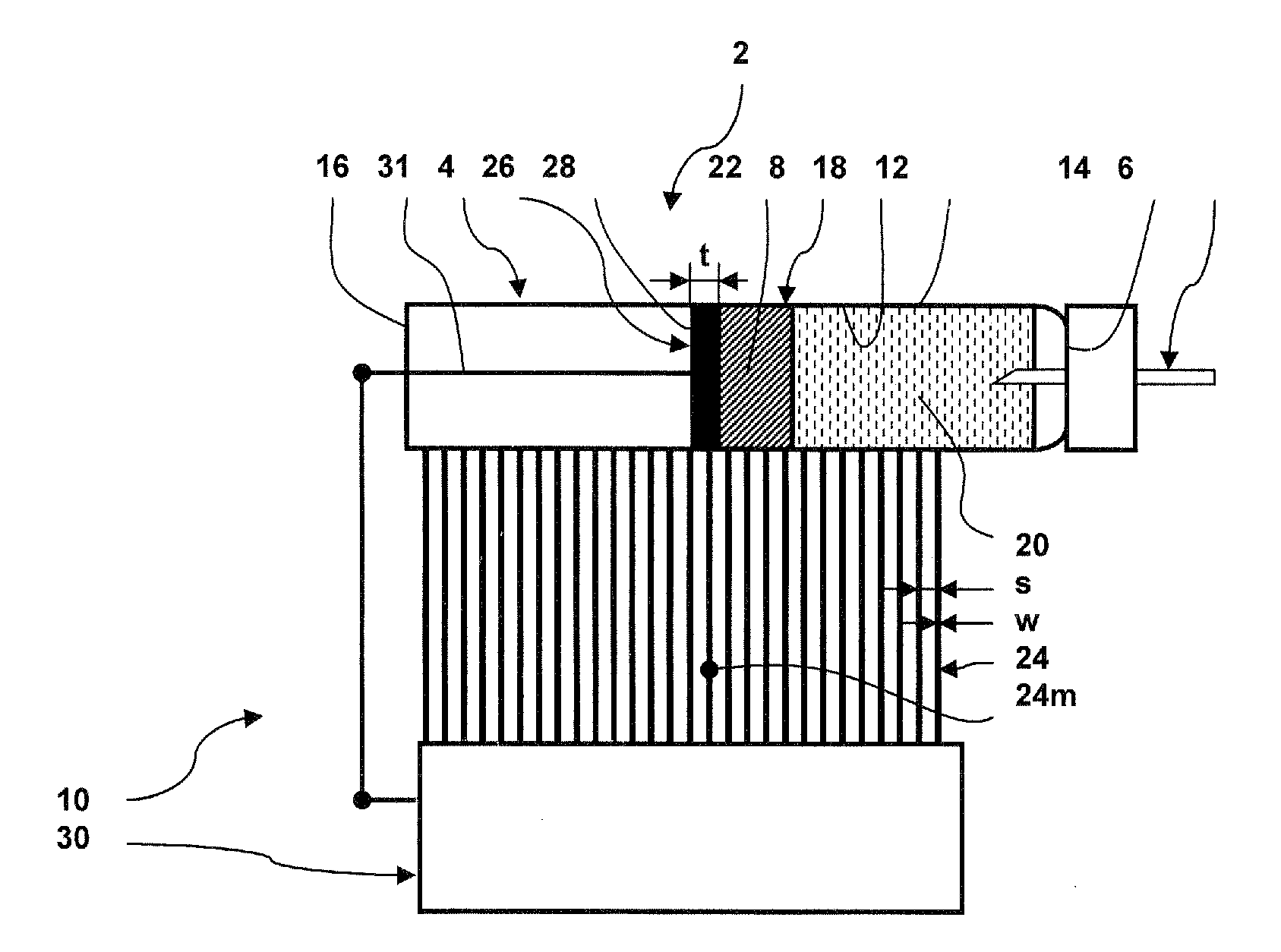
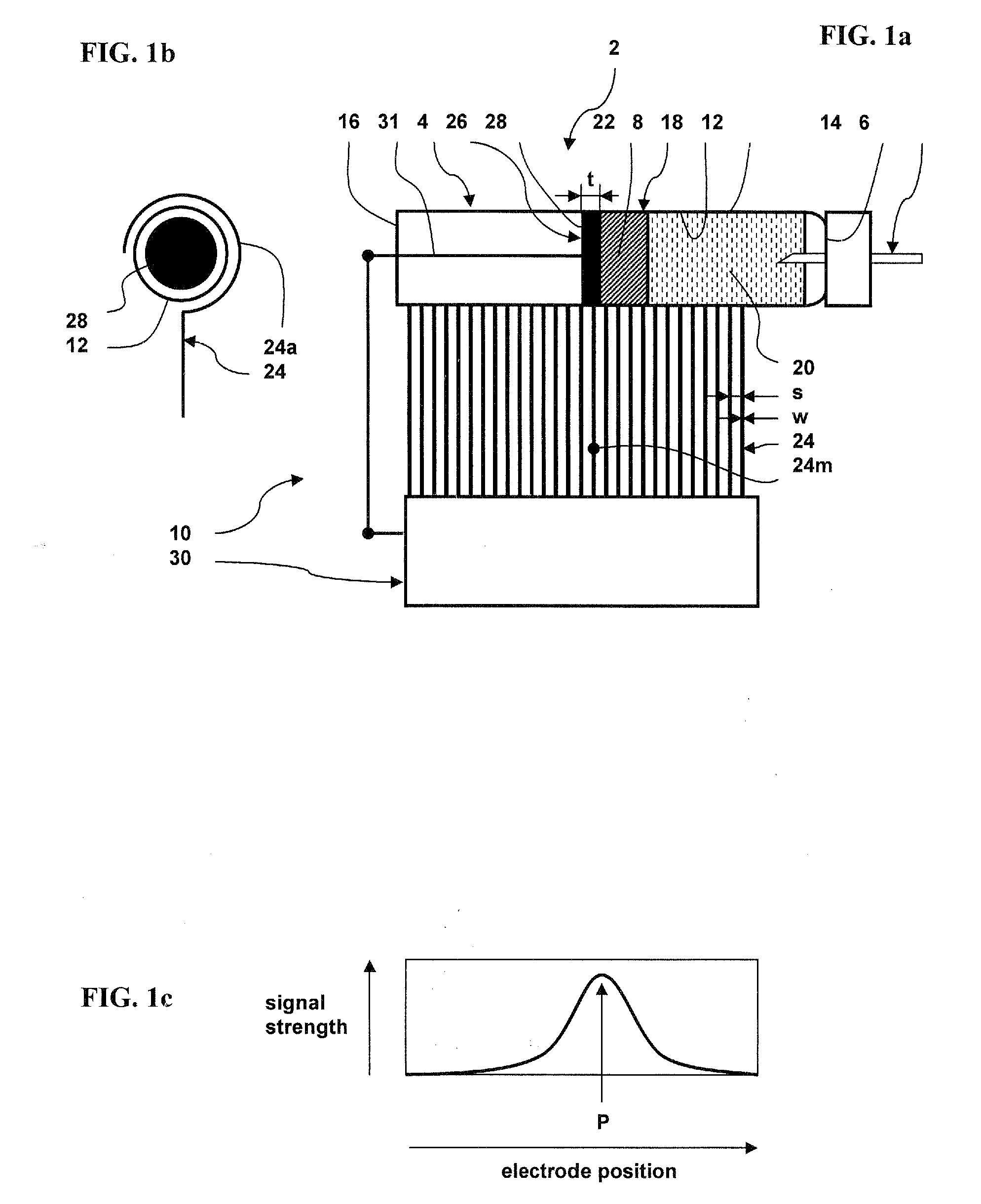
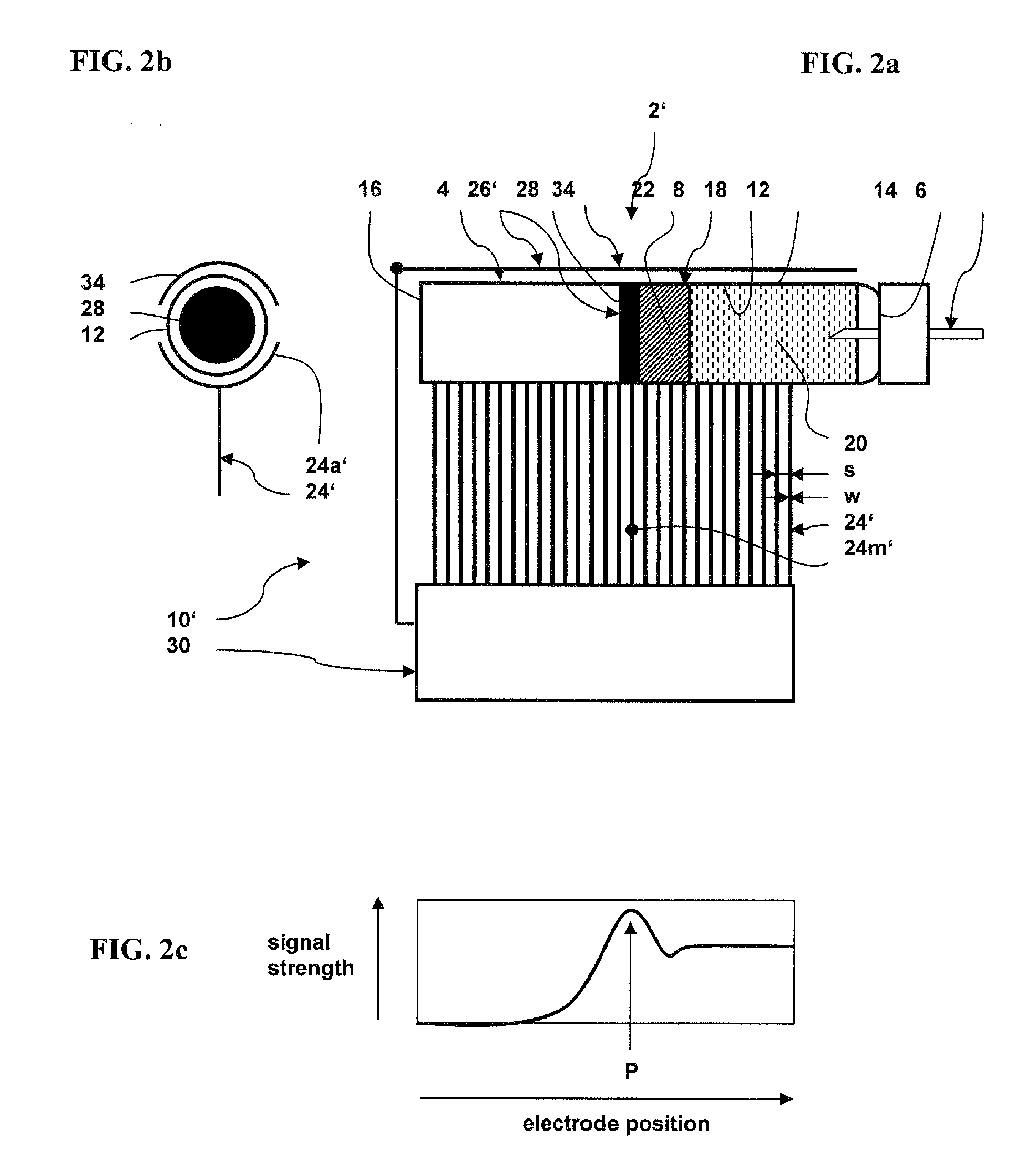
[0023]The container wall 4 comprises a tubular wall portion 12 extending from an outlet end 14 to an opposed plunger end 16 proximate a starting position of the plunger / piston 8 when the cartridge is full. The outlet end 14, tubular wall portion 12 and plunger / piston 8 define a chamber 18 storing a fluid 20 that is expelled though the outlet 6 when the plunger / piston is advanced towards the outlet end 14. The tubular wall portion 12 thus extends in a direction of displacement D of the plunger or piston and preferably has a cylindrical shape.

[0024]The cartridge 2, 2′, 2″ may for example be in the general form of a vial for the storage and delivery of a liquid medicine such as insulin, the cartridge being replaceably installed in a delivery system, for instance an insulin pump device. The cartridge may also be non-replaceable and refilled, for example through a valve or a seal, from a separate liquid source.

[0025]The outlet end 14 of the cartridge may for example be in a form of a cap...


PUM


Abstract

A cartridge (2) with a fill level detection system (10, 10′, 10″), the cartridge comprising a substantially rigid containing wall (4) having a tubular wall portion (12) surrounding a chamber (18) for receiving liquid therein, a plunger or piston (8) mounted inside the chamber and configured to seal one side of the chamber, the plunger or piston being displaceable in the chamber towards an outlet end (14) of the cartridge, characterised in that the fill level detection system comprises a plurality of discrete fixed electrodes (24, 24′) positioned along the tubular wall portion in a juxtaposed manner in a direction of displacement D of the plunger or piston (8), and a mobile electrode member (28) fixed to the plunger or piston and displaceable therewith.

Description

FIELD OF THE INVENTION[0001]The present invention relates to a cartridge for containing fluids, with a fill level detection system. The invention in particular relates to a cartridge for liquid medicinal products, such as insulin, glucagon, and growth hormones, the cartridge comprising a mobile piston or plunger for expelling the liquid or simply allowing a change in volume in the cartridge.BACKGROUND[0002]Cartridges with a piston or plunger are well-known in insulin pump systems whereby detection of the fill level of the cartridge is important to ensure that the pump system functions correctly and / or that the correct dosage is supplied and / or to signal replacement of the cartridge.[0003]Various cartridge fill level detection systems have been proposed as described in U.S. Pat. No. 5,704,922, U.S. Pat. No. 6,352,523, WO 2007 / 107558, and DE 102004040441.[0004]In U.S. Pat. No. 5,704,922, a syringe having electrical contacts points for metering doses is disclosed. A disadvantage of thi...

Claims


Application Information

Patent Timeline
Patent Type & Authority Applications(United States)
IPC IPC(8): G01F23/26G01B7/14
CPCA61J1/062A61M5/1452A61M5/1685A61M5/24A61M5/31511G01F23/268A61M2205/3317A61M2205/3389G01F23/265G01F23/266A61M2205/0233
Inventor SCHNIDRIG, JURG
Owner SENSILE MEDICAL AG
Learn More