Object Distance Deriving Device

a distance deriving and object technology, applied in the direction of distance measurement, instruments, television systems, etc., can solve the problems of inability to secure the eye imaging device, the size reduction of the eye imaging device adapted to cars, and the inability to accurately derive the object distance. , to achieve the effect of accurate derive the object distance and limited baseline length of the imaging devi

Inactive Publication Date: 2010-04-29
FUNAI ELECTRIC CO LTD +1
View PDF3 Cites 193 Cited by
  • Summary
  • Abstract
  • Description
  • Claims
  • Application Information

AI Technical Summary

Benefits of technology

[0009]An object of the present invention is to provide an object distance deriving device which uses imaging means and derives a distance of an object (object distance) from the imaging means based on a high-resolutio...

Problems solved by technology

This unavoidably increases the size of the entire imaging device.
Thus, for example, it is difficult to use a size-reduced compound-eye imaging device adapted to cars as an object distant deriving device using parallax described above.
Such compound-eye imaging device does not make it possible to secure a sufficient baseline length of about a few meters to 10 m or longer by using parallax.
This makes it impossible to obtain parallax between the unit images, and thus t...

Method used


Image

  • Object Distance Deriving Device
  • Object Distance Deriving Device
  • Object Distance Deriving Device

Examples


first embodiment

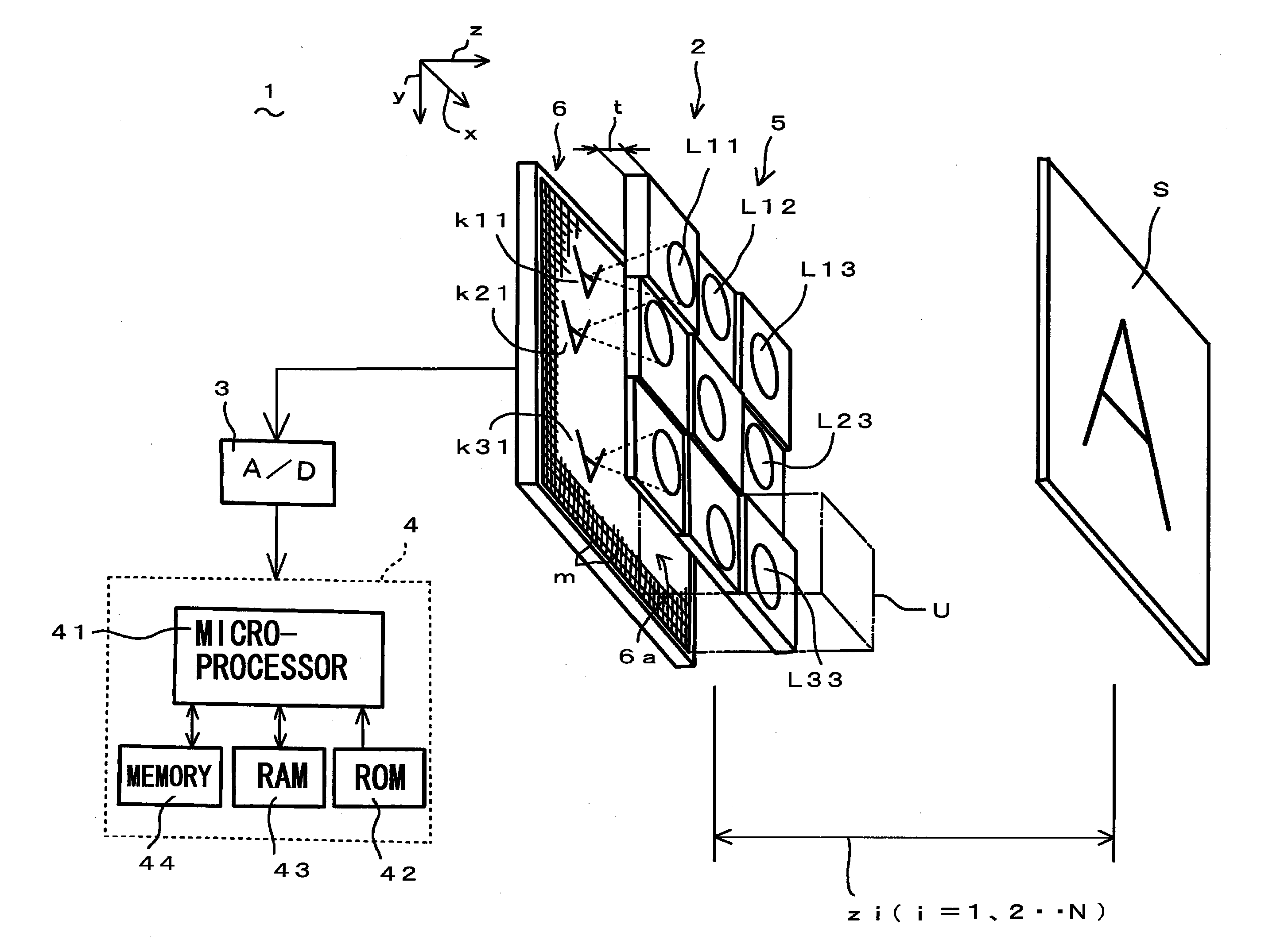
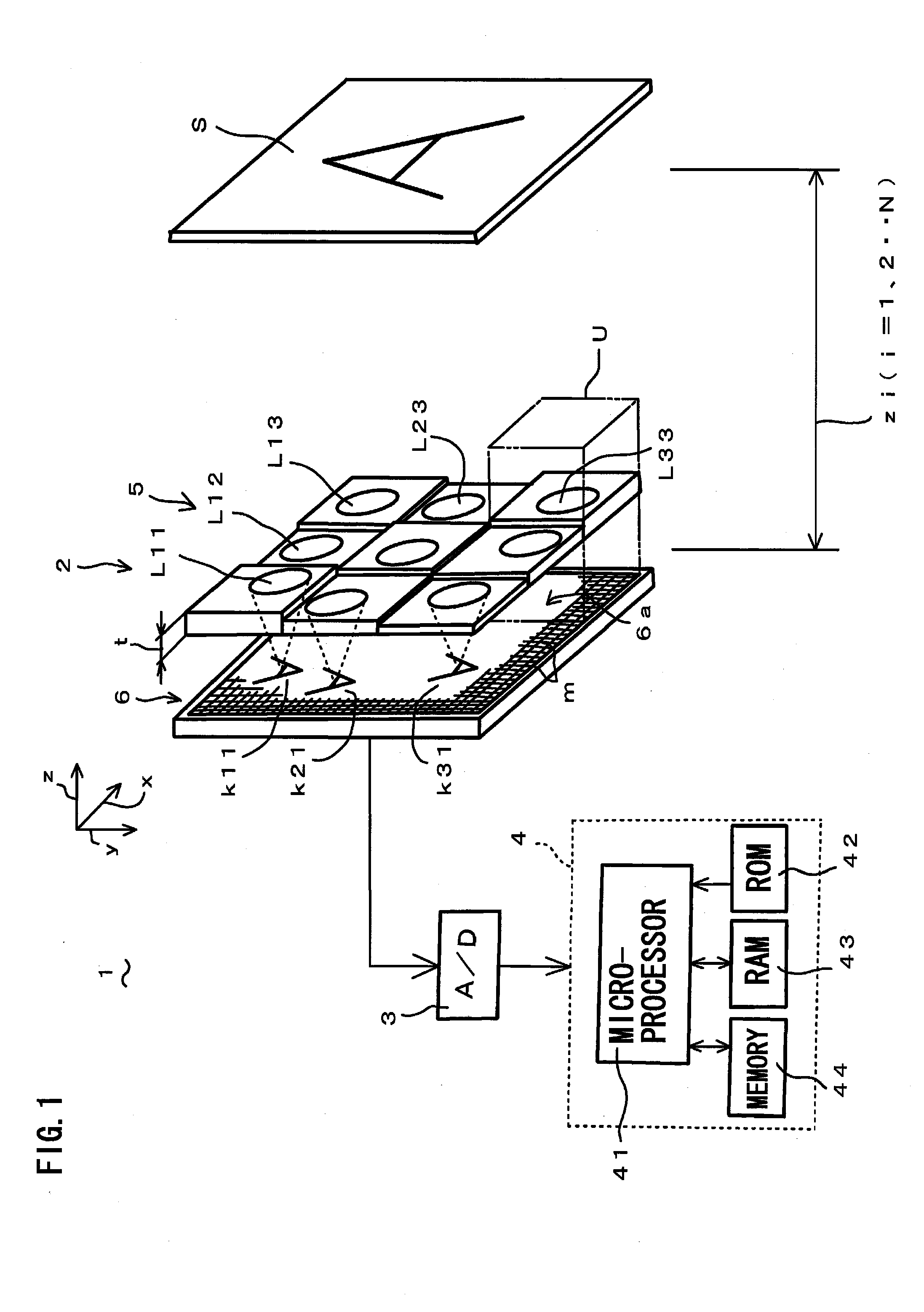
[0029]Referring to FIG. 1 to FIG. 8, an object distance deriving device 1 according to a first embodiment of the present invention will be described. FIG. 1 is a schematic view, partly in block form, of an object distance deriving device 1 of the present embodiment. As shown in FIG. 1, the object distance deriving device 1 comprises a compound-eye imaging device 2 (claimed “imaging means” or “compound-eye imaging means”) and a distance calculation unit 4 (claimed “distance calculating means”) mainly composed of a microprocessor 41 for receiving, via an A / D (Analog-to-Digital) converter 3, image information captured by the compound-eye imaging device 2, and for calculating a distance (object distance) z between an object (target object to be imaged) S and the compound-eye imaging unit 2 (more specifically optical lens array 5) based on the received and digitized image information. The object S shown is two-dimensional (flat-shaped) for simplicity of description, but can be three-dime...

second embodiment

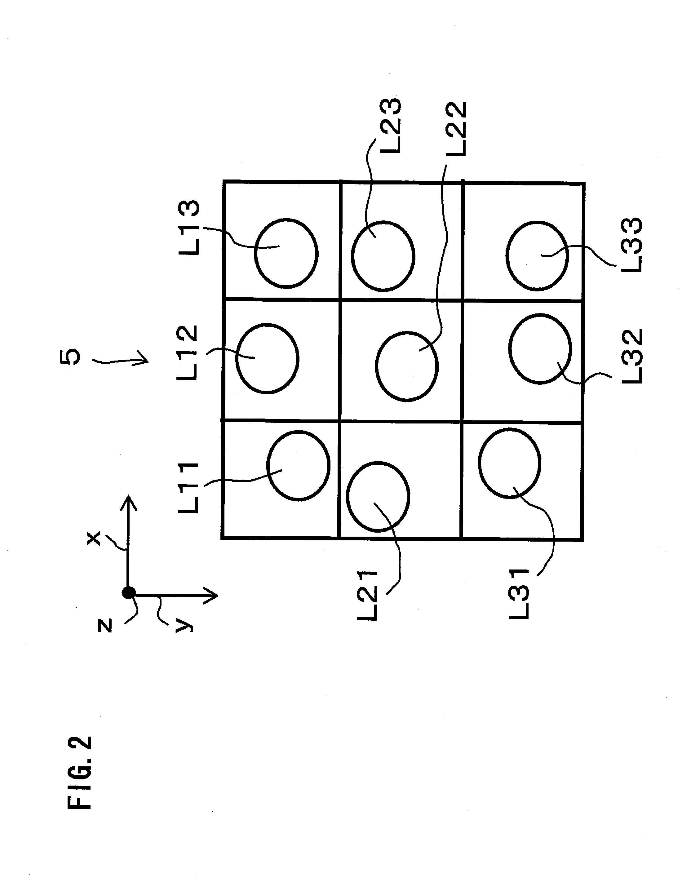
[0048]Hereinafter, an object distance deriving device according to a second embodiment of the present invention will be described. The object distance deriving device of the present embodiment is the same as the object distance deriving device 1 of the first embodiment, except that the arrangement of the optical lenses L11, L12 . . . L33 in the present embodiment is different from that in the first embodiment where the optical lenses of the compound-eye imaging device 2 are randomly arranged for the respective imaging units U. In the present embodiment, in order to increase a substantial amount of information of the captured images for deriving a more accurate object (target object) distance, the optical lenses L11, L12 . . . L33 are arranged to adapt to an optimum condition calculated by an optimizing method using an evaluation function to evaluate average errors of an object distance.

[0049]More specifically, the following equation (5) is an evaluation function C which represents a...


PUM


Abstract

An object distance deriving device comprises: a compound-eye imaging device having imaging units with optical lenses randomly arranged for the respective imaging units; and a distance calculation unit to calculate an object distance using images captured by the compound-eye imaging device. The distance calculation unit: sets temporary distances z (S1); calculates an imaging process matrix [Hz] according to a temporary distance z (S2); estimates a high-resolution image by super-resolution processing using the imaging process matrix [Hz] (S3); uses the estimated high-resolution image to calculate an evaluation value distribution E for evaluating the temporary distance z (S4); repeats steps S2 to S4 for all temporary distances z (S5); and determines, as an object distance, one temporary distance z giving a minimum evaluation value in the evaluation value distributions E. This makes it possible to accurately derive the object distance even if the baseline length of the compound-eye imaging device is limited.

Description

BACKGROUND OF THE INVENTION[0001]1. Field of the Invention[0002]The present invention relates to an object distance deriving device, and more particularly to an object distance deriving device which has imaging means and derives a distance of an object from the imaging means based on a high-resolution image estimated by super-resolution processing using images captured by the imaging means.[0003]2. Description of the Related Art[0004]An imaging device is known which comprises multiple optical lenses and an imaging element (photodetector) for capturing multiple images of an object (target object) that are formed by the optical lenses. It is known to derive a distance of the object from the imaging device by using parallax between images of the object captured by the imaging device (refer to e.g. Japanese Laid-open Patent Publication 2007-271301). In order to more accurately derive the distance of the object from the imaging device by using parallax, the baseline length between the op...

Claims


Application Information

Patent Timeline
IPC IPC(8): H04N9/47
CPCG01B11/026G01C3/08G02B27/58G02B7/38G02B3/0043
Inventor TANIDA, JUNHORISAKI, RYOICHINAKAO, YOSHIZUMITOYODA, TAKASHIMASAKI, YASUO
Owner FUNAI ELECTRIC CO LTD
Why Eureka
Try Eureka