
Edge-lighting LED backlight and LCD thereof

a technology of led backlight and lightemitting diodes, which is applied in the field of liquid crystal display technology, can solve the problems of difficult mass production and high cost, and achieve the effect of reducing the cost of backligh

Active Publication Date: 2010-04-29
BOE TECH GRP CO LTD
View PDF4 Cites 12 Cited by
  • Summary
  • Abstract
  • Description
  • Claims
  • Application Information

AI Technical Summary

Benefits of technology

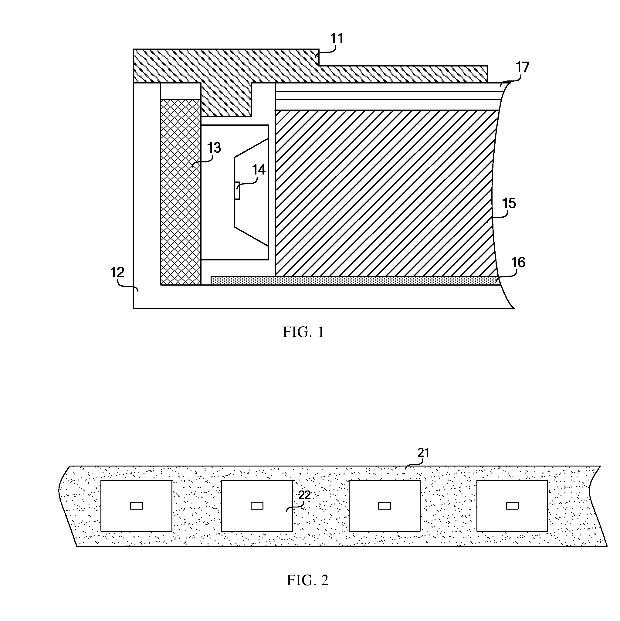
[0006]The subject of the present invention is to provide an edge-lighting LED backlight and LCD thereof to decrease the cost of the backlight.
[0010]In the above solution, the surface reflectance of the LED light bar is improved, the light loss is decreased and the utilization rate of light is improved by disposing the reflector between the LED light bar and the light guide plate, which decreases the quantity of the LEDs and the cost of the backlight.

Problems solved by technology

Therefore, the LED backlight in the large-sized LCD with the size of larger than 19″ has the advantages of lightness and thinness, and pollution-free etc., but it is difficult to achieve mass production as the cost is more expensive.

Method used


Image

  • Edge-lighting LED backlight and LCD thereof
  • Edge-lighting LED backlight and LCD thereof
  • Edge-lighting LED backlight and LCD thereof

Examples


first embodiment

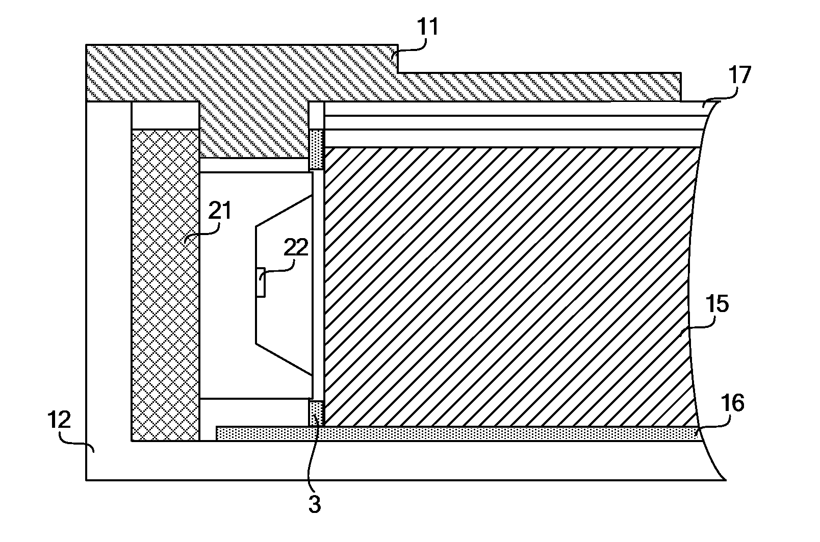
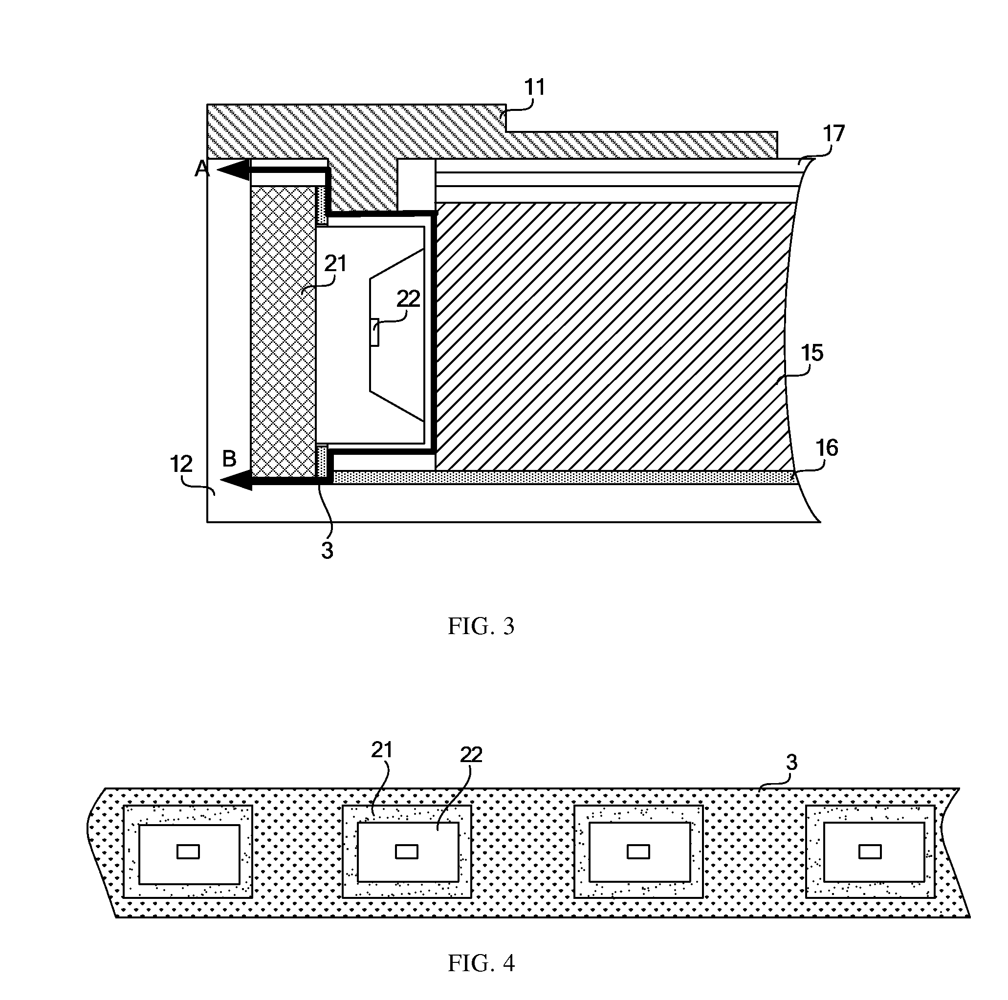
[0021]FIG. 3 is the structure view showing the edge-lighting LED backlight in the present invention. FIG. 4 is the view along a direction of A-B in FIG. 3. As shown in the FIG. 3 and FIG. 4, the holes are set on the reflector 3 to provide exit for the light. In this embodiment, the reflector 3 is attached to the LED light bar, and the LEDs 22 are infixed into the corresponding holes. The backlight improves the surface reflectance of the LED light bar by using the reflector 3, avoids the light loss of the surface of the LED light bar, increases effective reflecting area of the light and improves the utilization rate of light. Therefore, the quantity of the LEDs on the backlight is decreased while brightness of the backlight being kept.

second embodiment

[0022]FIG. 5 is the structure view showing the edge-lighting LED backlight in the present invention. The part front view of the reflector 3 in FIG. 5 is as shown in FIG. 4. In this embodiment, the reflector 3 is attached to a side of the light guide plate, ie. a light input surface. All the positions on the reflector 3 corresponding to the LEDs 22 have the holes, and the light emitting surface of the LEDs 22 are embedded into the holes of the reflector 3. The thickness of the reflector 3 may be increased so as to improve stability of the structure of the backlight.

[0023]When fixing, a thicker reflector 3 may be attached to the light input surface of the light guide plate 15, and light-emitting surface of the LEDs 22 are put into the holes of the reflector 3, avoiding directly touch between the light emitting surface of the LEDs and the light input surface of the light guide plate 15.

[0024]In the above embodiments, the reflector may be further disposed inside the up-frame 11, as show...


PUM

PropertyMeasurementUnit
impact strengthaaaaaaaaaa
structureaaaaaaaaaa
optical modelaaaaaaaaaa

Abstract

The present invention relates to an edge-lighting LED backlight and LCD. The edge-lighting LED backlight comprises an LED light bar and a light guide plate, wherein a reflector is disposed between the LED light bar and the light guide plate, holes are set on the reflector, and light emitted from the LED light bar enters into the light guide plate through the holes. An LCD comprises the above edge-lighting LED backlight. In the above solution, the surface reflectance of the LED light bar is improved, the light loss is decreased and the utilization rate of light is improved by disposing the reflector between the LED light bar and the light guide plate, which decreases the quantity of the LEDs and the cost of the backlight.

Description

CROSS-REFERENCE TO RELATED APPLICATIONS[0001]This application claims priority to Chinese Patent Application No. 200810225007.8, filed on Oct. 23, 2008, entitled “EDGE-LIGHTING LED BACKLIGHT AND LCD”, which is incorporated herein by reference in its entirety.FIELD OF THE TECHNOLOGY[0002]The present invention relates to a liquid crystal display technology field, and particularly to an edge-lighting light-emitting diode (LED) backlight and liquid crystal display (LCD) which may improve overall light effect.BACKGROUND OF THE INVENTION[0003]In an LCD device, LED backlight is increasingly popular with LCD device manufacturers depending on its advantages of lightness and thinness, good resistant of impact strength and vibratility, good color rendition, pollution-free and being droved by low voltage and direct current. In an LED backlight, a lighter edge-lighting LED backlight attracts more attention. And the LED backlight in a small and medium-sized LCD is rapidly replacing cold cathode fl...

Claims


Application Information

Patent Timeline
Patent Type & Authority Applications(United States)
IPC IPC(8): G02F1/1335G02F1/13357
CPCG02B6/0083G02B6/0031
Inventor WANG, QINGJIANGZHAO, XINGXINGSUN, XIAOBINWAN, LIFANGZHANG, LILEIWANG, GANGSHAO, XIBIN
Owner BOE TECH GRP CO LTD
Learn More