Marker generating and marker detecting system, method and program

a marker generation and marker technology, applied in the field of marker generating and marker detecting systems, methods and programs, can solve the problems of low detection speed or instability, relative unreliability, and pattern confusion with each other, so as to improve the reliability of object detection, prevent misdetection, and reduce the difficulty of detection

Active Publication Date: 2010-04-29
NEC CORP
View PDF12 Cites 19 Cited by
  • Summary
  • Abstract
  • Description
  • Claims
  • Application Information

AI Technical Summary

Benefits of technology

[0033]A first effect is that reliability of object detection can be improved. The reason thereof is that a marker is designed by observing a background and avoiding similar patterns. Since the marker needs not be complicated more than necessary, an imaging device with comparatively low resolution may be used without failure in reading of a marker's fine structure, and misdetection is prevented.
[0034]A second effect is that there is no need for a trial-and-error process or a skilled person in designing a marker. The reason thereof is that a background is observed and a marker is automatically designed based on the observation.
[0035]A third effect is that cost for disposing a marker can be reduced. The reason thereof is that since a marker can be automatically generated as a distinctive graphic pattern unlikely to be confused with a background, visual discriminability can be achieved without relying on a marker material such as a reflector or a light-emitting element.
[0036]A fourth effect is that even when the positional relationship between a marker and an imaging device is unrestricted, no reduction of accuracy or speed in detection is experienced. The reason thereof is that since a marker is designed by performing observation through a geometrical invariant unaffected by geometrical distortion due to a positional relationship relative to an object, and designing the marker so that the geometrical invariant is dissimilar to a background pattern, there is no possibility that the marker matches the background pattern by chance due to geometrical distortion, and in addition, marker detection can be achieved without any special consideration in detecting a marker depending upon variation in positional relationship with respect to an object by, for example, correcting geometrical distortion or making a match taking account of distortion.
[0037]A fifth problem is that inexpensive implementation is possible without the need for an imaging device with high resolution or a decoder for a more complicated marker. The reason thereof is that since the least required graphical discrimination between a marker and a background pattern may be sufficient, the need for complicating a marker more than necessary is eliminated and it is not always necessary to embed a redundant code into a marker.

Problems solved by technology

The object detection scheme such as that in Patent Document 1 employing no marker eliminates the need of a marker to be attached, whereas it poses a problem that it is relatively unreliable, has a low detection speed or is unstable.
However, it poses a problem that once a graphic pattern similar to that of the predefined marker appears in a background by chance, these patterns are confused with each other.
These schemes, however, increase cost of the marker, nevertheless still potentially pose a problem similar to that in the method disclosed in Patent Document 2 in a case that a pattern similar to the form of the marker appears in a background by chance or the marker is placed in circumstances, such as outdoors, containing disturbance that may impair uniqueness of the form of the marker.
Furthermore, since the marker may be observed with geometric distortion due to the degree of freedom in positioning a camera in imaging, it is necessary to prepare a detection scheme taking account of such distortion.
In addition to an increase of computational cost for detection taking account of geometrical distortion, it is likely to increase a possibility that the distorted marker becomes similar to a background pattern by chance.
Whereas the schemes can significantly reduce the possibility of over-detection of a marker from a background, subtle graphical information on the marker must be visualized on a video image, which may cause misdetection of the marker, so that imaging coverage must be reduced or resolution of an imaging device must be increased, resulting in a presumable increase of cost for implementing a decoder and reduction of the detection speed.

Method used


Image

  • Marker generating and marker detecting system, method and program
  • Marker generating and marker detecting system, method and program
  • Marker generating and marker detecting system, method and program

Examples


first embodiment

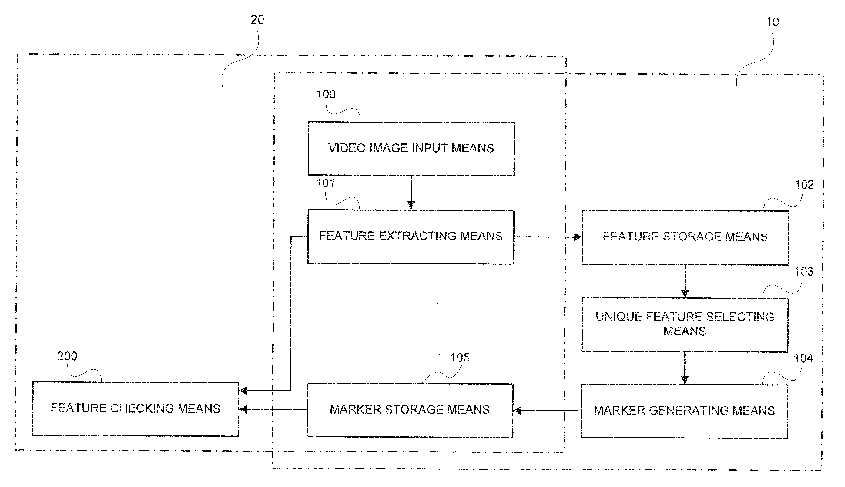
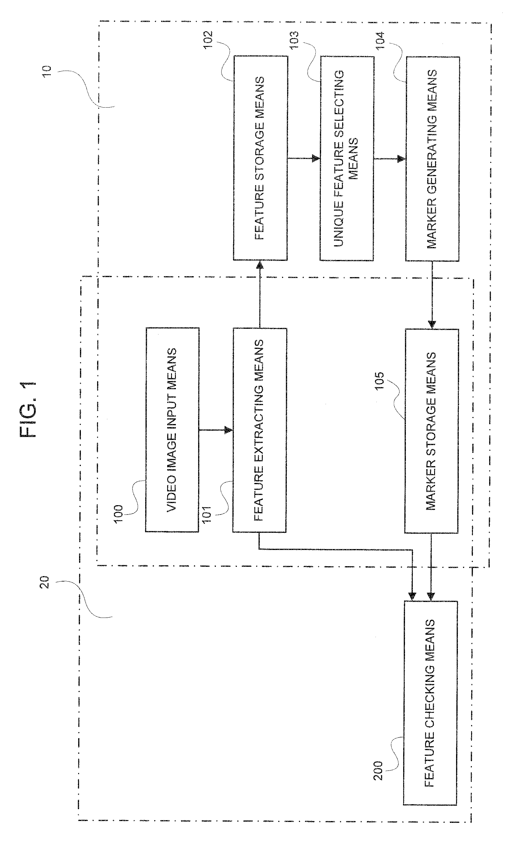
[0120]A first embodiment relates to the graphic marker generating section 10. The graphic marker generating section 10 is comprised of video image input means 100, feature extracting means 101, feature storage means 102, unique feature selecting means 103, and marker generating means 104.

[0121]The graphic marker generating section 10 is for, before actually attaching a marker to an object and performing marker detection, in an environment in which marker detection is applied, observing a background pattern, that is, a scene excluding the object to be detected, obtaining an occurrence frequency distribution of features, and based on the distribution, outputting a graphic pattern as a marker pattern that is never present in the background pattern.

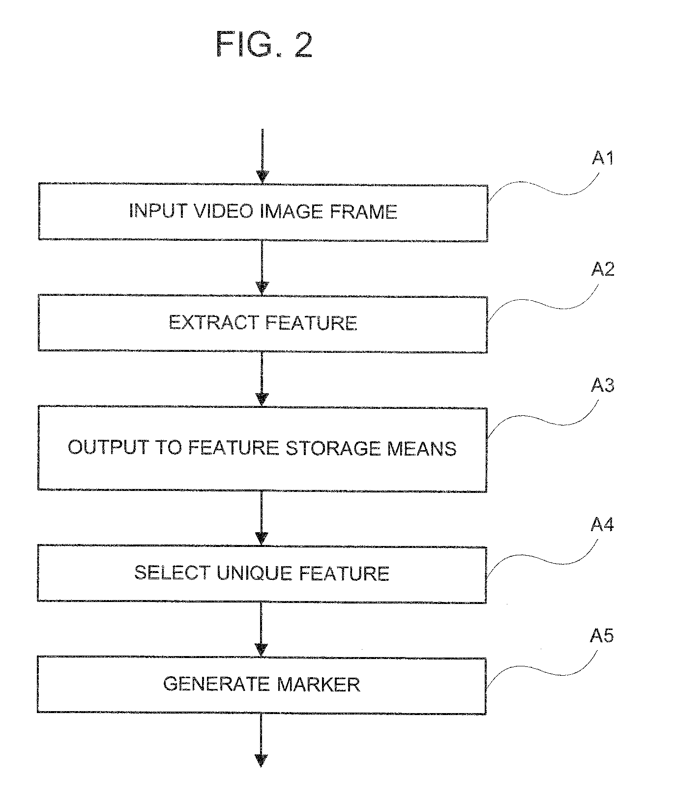
[0122]The means constituting the graphic marker generating section 10 generally operate in a manner as described below.

[0123]The video image input means 100 inputs a video image containing an image of an environment to which the present inven...

second embodiment

[0145]Next, a second one of the best modes for carrying out the present invention will be explained in detail with reference to the accompanying drawings.

[0146]The graphic marker detecting section 20 of the present invention will now be explained in detail with reference to FIG. 1. The present invention relates to detection of a marker pattern from a scene.

[0147]The second embodiment relates to the graphic marker detecting section 20. The graphic marker detecting section 20 is comprised of video image input means 100, feature extracting means 101, marker storage means 105, and feature checking means 200.

[0148]These means generally operate in a manner as described below.

[0149]The video image input means 100 and feature extracting means 101 operate similarly to those in the first embodiment.

[0150]The marker storage means 106 stores therein marker patterns generated beforehand. When a marker pattern generated by the graphic marker generating section 10 in the first embodiment is used, ...

example 1

[0159]Next, a specific example will be explained.

[0160]First, an operation of marker design will be particularly explained with reference to a case in which a graphical feature is employed.

[0161]For a video image scene as shown in FIG. 6, feature point groups as indicated by shown in FIG. 7 are generated. An exemplary operation of selecting a unique feature from a quantized feature space will be explained hereinbelow. FIG. 8 shows a mesh having 8×8 cells obtained by mapping feature point groups onto a feature space and quantizing the invariant space from the result. In FIG. 8, a filled-in mesh cell indicates an occurrence frequency of non-zero, that is, indicates that a projection of a feature point is present within the mesh cell, and a non-filled mesh cell indicates a mesh cell having an occurrence frequency of zero.

[0162]According to the first embodiment, a unique feature is selected from the non-filled mesh cells. An example in which a center of a non-filled mesh cell is defined...


PUM


Abstract

A marker generating system is characterized in having a special feature extracting element that extracts a portion, as a special feature, including a distinctive pattern in a video image not including a marker; a unique special feature selecting element that, based on the extracted special feature, selects a special feature of an image, as a unique special feature, that does not appear on the video image; and a marker generating element that generates a marker based on the unique special feature.

Description

TECHNICAL FIELD[0001]The present invention relates to marker generating and marker detecting system, method and program.BACKGROUND ART[0002]Examples of conventional video image-based object detection systems are disclosed in Patent Documents 1-7.[0003]The conventional video image-based object detection systems operate as follows:[0004]Specifically, a scheme disclosed in Patent Document 1 enables detection of an object having any shape and estimation of its attitude by sophisticating object detection without attaching a predefined marker elaborately designed beforehand for facilitating or speeding up detection processing. The object detection scheme such as that in Patent Document 1 employing no marker eliminates the need of a marker to be attached, whereas it poses a problem that it is relatively unreliable, has a low detection speed or is unstable. A scheme disclosed in Patent Document 2 solves such a problem by attaching a marker having a distinctive graphic pattern that is relati...

Claims


Application Information

Patent Timeline
Patent Type & Authority Applications(United States)
IPC IPC(8): G06K9/00G06K9/46G06V10/422
CPCG06K9/468G06K2009/0059G06T7/60G06T7/401G06K2009/3225G06T7/11G06T7/41G06T7/194G06V20/95G06V10/245G06V10/422G06V20/48G06F18/24G06T2207/30204
Inventor NAKAJIMA, NOBORU
Owner NEC CORP
Why Eureka
Try Eureka