Method of assembling a refrigerating compressor

a technology of refrigerating compressor and compressor body, which is applied in the direction of engine lubrication, rotary or oscillating piston engines, piston engines, etc., can solve the problems of deformation of the shell ring in the plane, affecting the alignment of the bearings and thus the reliability of the machine, etc., and achieves the effect of simple and economical

Inactive Publication Date: 2010-04-29
DANFOSS COMML COMPRESSORS
View PDF9 Cites 0 Cited by
  • Summary
  • Abstract
  • Description
  • Claims
  • Application Information

AI Technical Summary

Benefits of technology

[0011]It is an aim of the present invention to overcome these disadvantages and an object of the invention to provide a method of assembling a refrigerating compressor which is simple and economical while at the same time allowing the bearing support to be attached firmly to the shell ring without giving rise to any out-of-roundness of the shell ring in the plane of attachment of the bearing support.
[0018]Thus, the bearing support is held firmly in the shell ring by the elasticity of the latter. This arrangement makes it possible to avoid creating spot welds of specific size, and therefore makes it possible to simplify the method of assembling the refrigerating compressor.
[0019]Furthermore, this method of attaching the bearing support into the shell ring makes it possible to maintain the roundness of the latter in the plane of attachment of the bearing support.
[0027]This spot weld is then created essentially to prevent the bearing support from shifting as a result of vertical loadings, for example when the latter is being moved around.

Problems solved by technology

As a result, the various spot welds are subjected to a fatigue cycle which means that they have to be dimensioned accordingly.
If the welds are inadequately dimensioned that will, after a period of operation, adversely affect the alignment of the bearings and thus the reliability of the machine.
However, this force-fitting of the bearing support into the shell ring would lead to deformation of the shell ring in the plane of attachment of the bearing support.

Method used


Image

  • Method of assembling a refrigerating compressor
  • Method of assembling a refrigerating compressor
  • Method of assembling a refrigerating compressor

Examples


Embodiment Construction

)

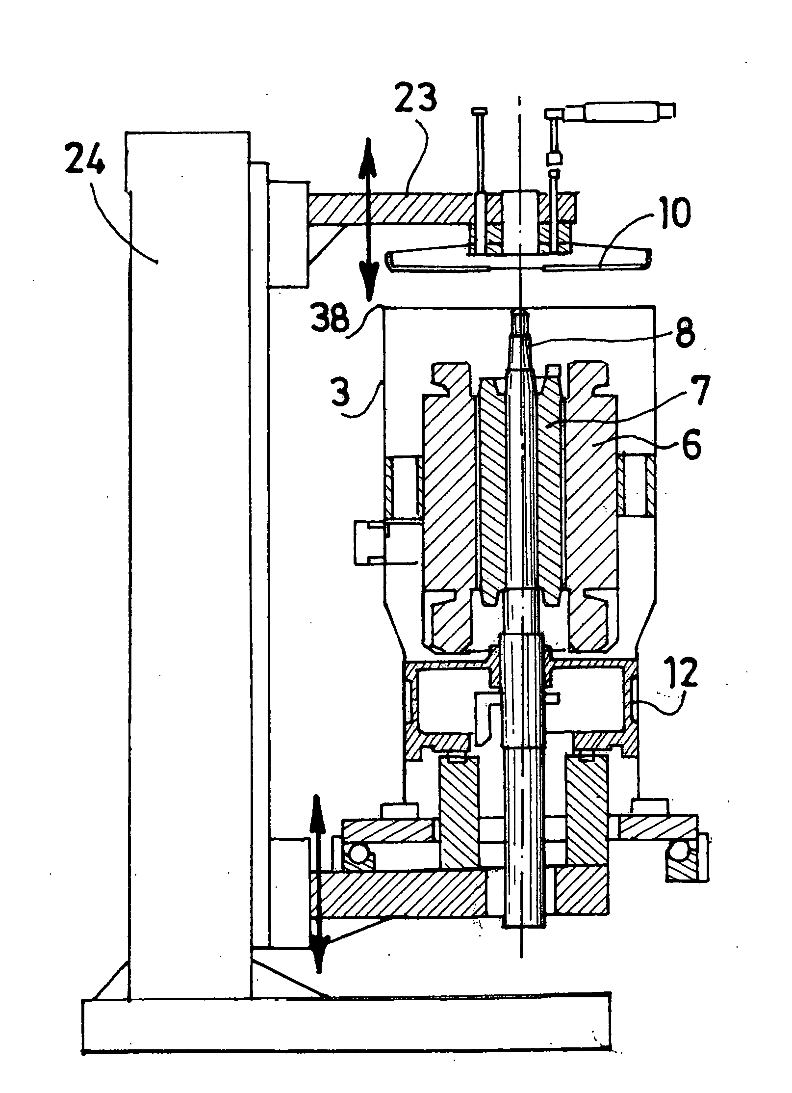
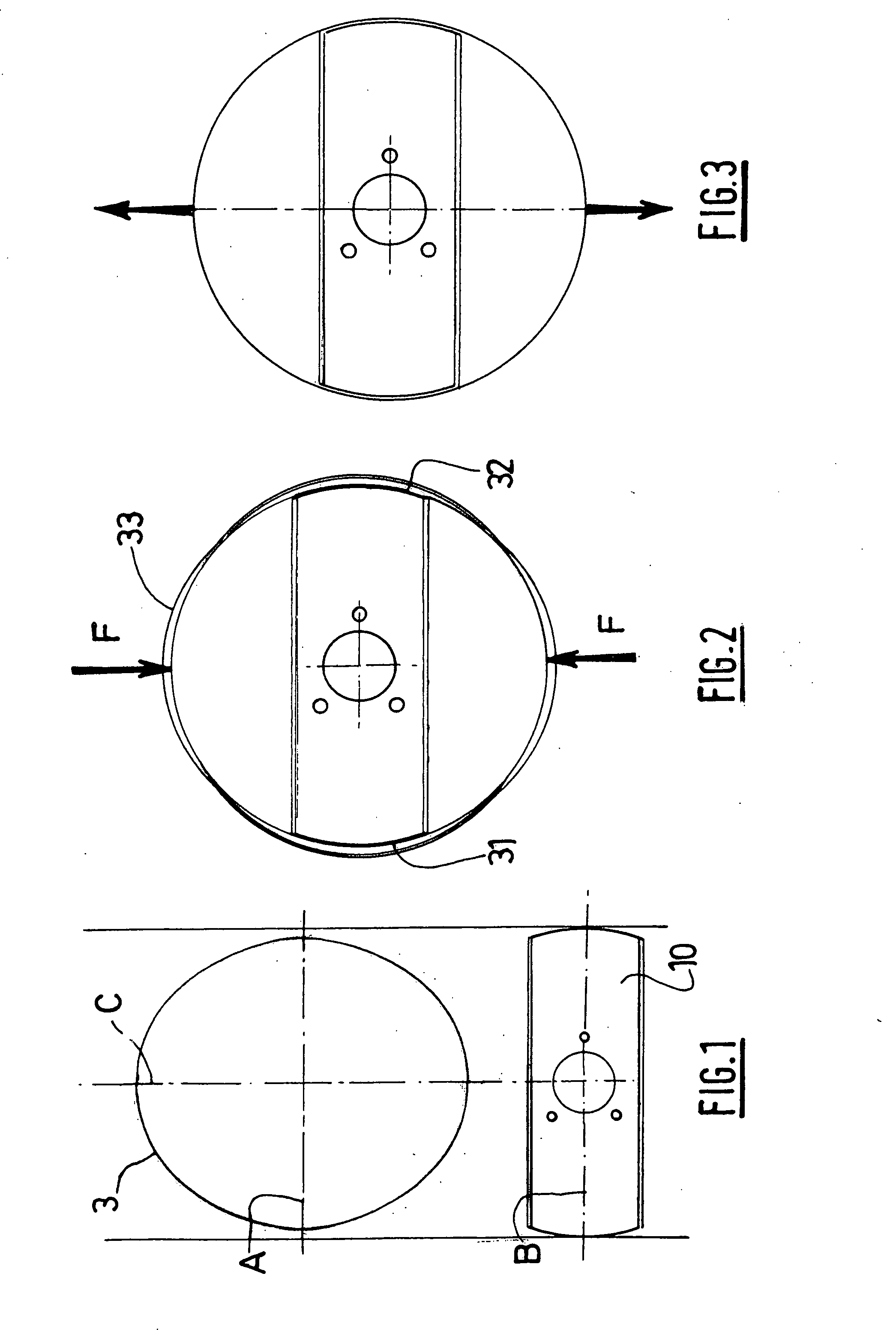
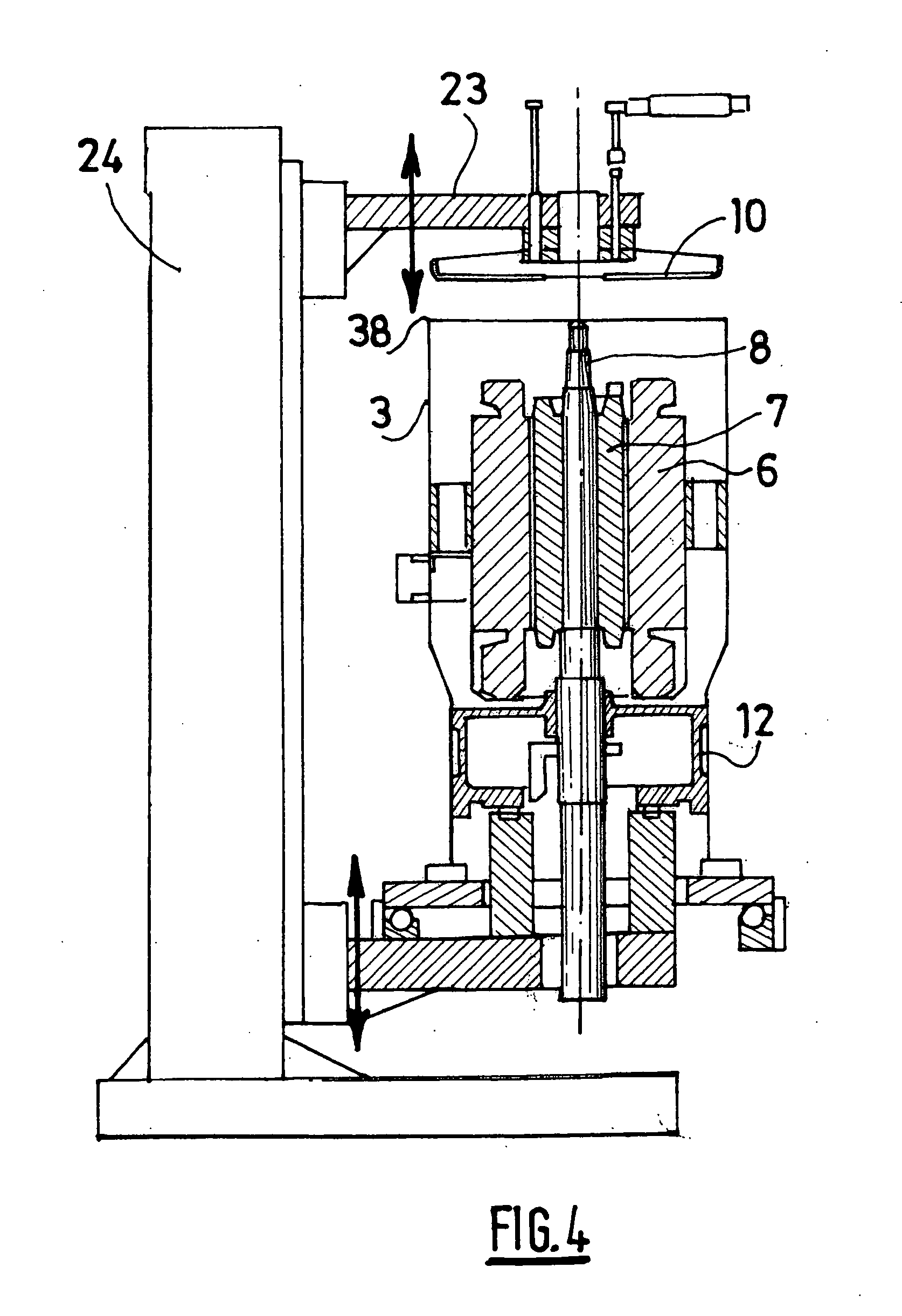
[0051]The drive shaft 8 is guided with respect to the other components of the compressor by at least one bottom bearing 9 created in a bearing support 10 of substantially rectangular shape. The bearing support 10 is attached to the interior wall of the shell ring, near the base 5, along an axis substantially perpendicular to the axis 30 of the shell ring 3. As shown in FIG. 2, the transverse edges 31, 32 of the bearing support 10 respectively extend along an arc of a circle 33.

[0052]The method of assembling this scroll compressor will now be described.

[0053]The method of assembly according to the invention is depicted in FIGS. 1 to 8 and comprises the following steps consisting in:[0054]supplying a shell ring 3 which, in the plane of attachment of the bearing support 10, has a cross section of oval overall shape comprising, as depicted in FIG. 1, a minor axis A along which the bearing support 10 is intended to be mounted, and a major axis C, the length of the minor axis A being les...


PUM

PropertyMeasurementUnit
lengthaaaaaaaaaa
pressureaaaaaaaaaa
diameteraaaaaaaaaa

Abstract

A compressor comprising a sealed chamber delimited laterally by a shell, a drive shaft housed in the shell and guided relative to the other parts of the compressor via at least one bearing provided in a bearing support fixed to the internal wall of the shell. The method comprises steps consisting in supplying a shell have, in the fixing plane of the bearing support, an oval section comprising a small axis to which the bearing support is intended to be mounted, exerting a pressure on the shell in order to elastically deform it so as to increase the length of its small axis, inserting and positioning the bearing support in the fixing plane of the latter, and ceasing to exert a pressure on the shell so that the latter tends to elastically return to its original form and grip the bearing support.

Description

BACKGROUND OF THE INVENTIONDescription of the Prior Art [0001]The present invention relates to a method of assembling a refrigerating compressor and to a refrigerating compressor.[0002]Document FR 2 885 966 describes a refrigerating compressor comprising:[0003]a sealed chamber laterally delimited by a substantially cylindrical shell ring the two ends of which are closed by a cover and by a base, respectively,[0004]an electric motor housed in the shell ring, the electric motor comprising a stator, and a rotor secured to a drive shaft, the drive shaft being guided with respect to the other components of the compressor by at least one bearing created in a bearing support attached to the interior wall of the shell ring, near the base.[0005]The purpose of the bearing support is to transmit to the shell ring of the compressor the loads applied to the bearing that guides the drive shaft.[0006]The bearing support is attached to the shell ring by welding. Hence, the loads applied by the driv...

Claims


Application Information

Patent Timeline
Patent Type & Authority Applications(United States)
IPC IPC(8): F04B35/04B23P15/00
CPCF04C18/02Y10T29/4924F04C2230/60
Inventor GENEVOIS, DAVIDGINIES, PIERREPFISTER, JEAN MICHEL
Owner DANFOSS COMML COMPRESSORS
Why Eureka
Try Eureka