
Air sampling system and method for calibration

a sampling system and air sampling technology, applied in the direction of chemical indicators, instruments, optical radiation measurement, etc., can solve the problems of unsatisfactory individual use of tubes, unsatisfactory emergency situations of military, civil defense, first responders, etc., to prevent external contamination and prevent external contamination of the system

Inactive Publication Date: 2010-04-29
KIROLLOS KIROLLOS SALAMA +1
View PDF2 Cites 11 Cited by
  • Summary
  • Abstract
  • Description
  • Claims
  • Application Information

AI Technical Summary

Benefits of technology

[0005]More particularly, it is an object of the present invention to provide an air sampling system as previously mentioned having simple and reliable components which operate in an unobstructive manner.
[0034]As far as each of the parallel sampling devices require a particular airflow and a total sampling volume, the total airflow is drawn by the pump at a preset vacuum level and particular airflows for each sampling device is adjusted by an adjustable aerodynamic resistance. Thus, the total airflow of the air sampling system drawn by the pump is a sum of all individual adjusted airflows. As the sampling time for all components of the system is the same, all sampling devices should be calibrated in a dynamic regimen with their particular aerodynamic flow resistances to achieve the required total sampling volume for each device. The system is calibrated in such a manner that each device shares part of the total airflow drawn from the pump in a wide range of vacuum settings. This allows the use of different pumping devices that can provide a required sampling vacuum for predetermined time intervals, resulting in the same total air sampling volume. The system is flexibly designed to use an electric pump, a Venturi pump or a hand / foot driven pump provided that the total sampling volume and time are the same and the shared particular flows are within the predetermined (during the calibration) ratio.

Problems solved by technology

Further, simultaneous determination of chemical warfare agents is a complex analytical task.
Detector tubes for several classes of chemical warfare agents have been developed, but the synchronized use of those tubes is very complicated.
Moreover, most known detector tubes require different analytical procedures resulting in several necessary steps for processing the air sample.
The length of time necessary for using each type of tube renders the individual use of tubes unsatisfactory for military, Civil Defense, and first responder's personnel during emergency situations.

Method used


Image

  • Air sampling system and method for calibration
  • Air sampling system and method for calibration
  • Air sampling system and method for calibration

Examples


Embodiment Construction

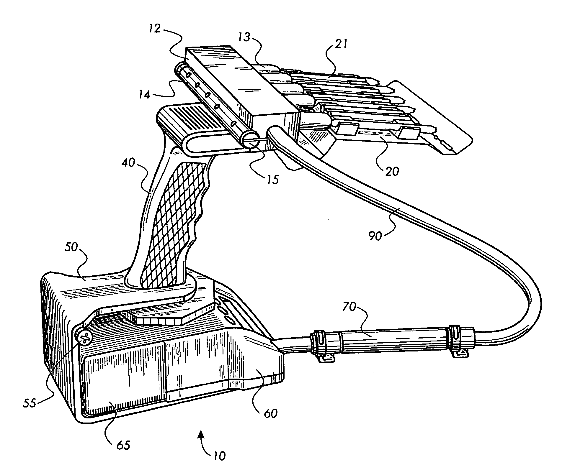
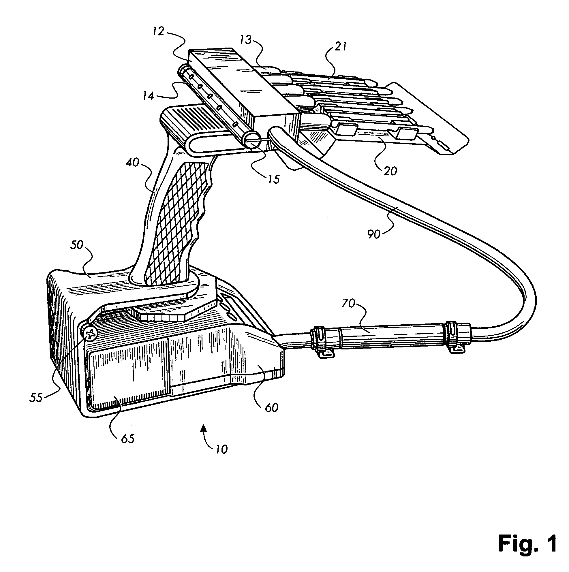
[0058]Referring now to the drawings in which like elements are designated by the same reference number throughout, there is shown in FIG. 1 a perspective view of the air sampling system 10 of the present invention. A pistol grip handle 40 provides a universal one-hand handle facilitation equipped with the capability of interchangeable components of vacuum pumps and extensions for collecting and sampling air from remote locations. On the top side of handle 40 is removably affixed sampling head 12. Sampling head 12 has a plurality of branches assembled on the front side with connecting sockets 18 and nipples 13 made preferably from flexible material such as rubber, soft plastic etc. The sockets 18 and nipples 13 face the sampling point and are connected to the sampling media through the sampling device 21. The number of the sockets 18 and nipples 13 can vary and is preferably more than two. Sampling devices 21 are directed forward towards an area from which an air sample is to be samp...


PUM

PropertyMeasurementUnit
diameteraaaaaaaaaa
flow ratesaaaaaaaaaa

Abstract

A chemical detection system includes detectors connected to a pump via a filter and hosing. The filter prevents the interior of the pump from internal contamination from a chemical or toxic agent. The airflow through the detector may be varied by an adjustable orifice. A pistol grip for holding the system and operating it is balanced with respect to a center of gravity.

Description

[0001]The present application relates to and claims priority from U.S. patent application Ser. No. 10 / 702,807 filed on Nov. 6, 2003.FIELD OF INVENTION[0002]This invention relates to an active type of air sampling device for simultaneously sampling several air contaminants. More particularly, the invention relates to a colorimetric type air sampling device that simultaneously analyzes an air sample and alerts an operator when one or more types of contaminants are present in the sampled air.BACKGROUND OF INVENTION[0003]There is an increased demand for devices that quickly and simultaneously detect and quantify highly toxic substances in air, particularly chemical warfare agents. The detection and quantification of chemical warfare agents require a wide variety of highly sensitive and fast responding reagents. Further, simultaneous determination of chemical warfare agents is a complex analytical task. Detector tubes for several classes of chemical warfare agents have been developed, bu...

Claims


Application Information

Patent Timeline
Patent Type & Authority Applications(United States)
IPC IPC(8): G01N35/10G01N1/22G01N31/00G01N31/22
CPCG01N1/2214G01N2001/247G01N1/24G01N1/2273
Inventor KIROLLOS, KIROLLOS SALAMAMIHAYLOV, GUEORGUI MILEV
Owner KIROLLOS KIROLLOS SALAMA
Learn More