Meniscal repair systems and methods

Active Publication Date: 2010-04-29
CAYENNE MEDICAL INC
37 Cites 58 Cited by

AI-Extracted Technical Summary

Problems solved by technology

However, over time, it has become known in the field that removing substantial portions of the meniscus often accelerates the onset of osteoarthritis and other complications which develop when the shock absorbing meniscuses in the knee are absent.
These techniques involve several access ports into the surgical site, and several instrument exchanges during the procedure, increasing surgical time and complexity.
This is a much easier meth...

Method used

[0047]FIGS. 11-13 illustrate three alternative needle embodiments, wherein the transfer needle 28 and the catch needle 30 are curved, rather than straight, as in the embodiment illustrated in FIGS. 1-10. Curves of the type disclosed in FIGS. 11-13 may be used to facilitate maneuvering beneath the femoral condyles.
[0050]The bevel orientation of the needles is currently fixed. However, the bevels can be changed in order to make the device easier to use.
[0052]Within the scope of the present invention, it is possible to add a tag or barb onto the end of the suture 34, which will provide a good piercing point, as an alternative to the c...

Benefits of technology

[0010]The present invention comprises an all suture approach having the ease of a single working portal, a pre-tied knot, and a single handed device that ...

Abstract

A device for repairing a tear in a portion of tissue comprises a proximal actuator portion, a transfer needle extending distally from the proximal actuator portion and a catch needle extending distally from the proximal actuator portion. A suture needle is disposed in the transfer needle, and is extendable from the transfer needle toward the catch needle and retractable from the catch needle toward the transfer needle. An extendable catch plunger is disposed in the catch needle for capturing suture therein when it is transferred from the transfer needle. A retractable insertion sheath is provided for covering the transfer needle and the catch needle when the device is inserted into a procedural site. A depth limiting apparatus limits the depth of insertion of the needle into the procedural site.

Application Domain

Technology Topic

Suture needlesSuturing needle +6

Image

  • Meniscal repair systems and methods
  • Meniscal repair systems and methods
  • Meniscal repair systems and methods

Examples

  • Experimental program(1)

Example

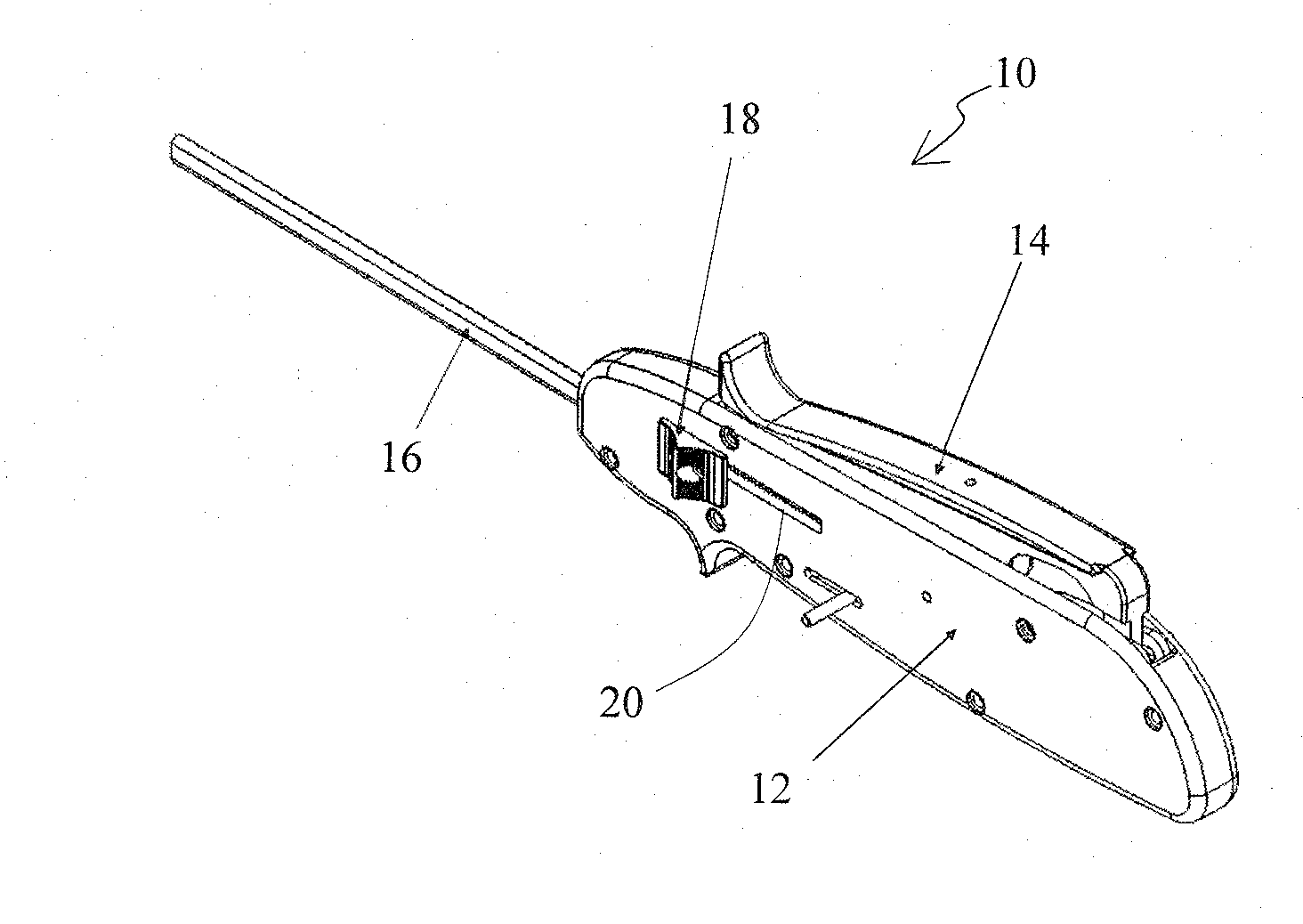
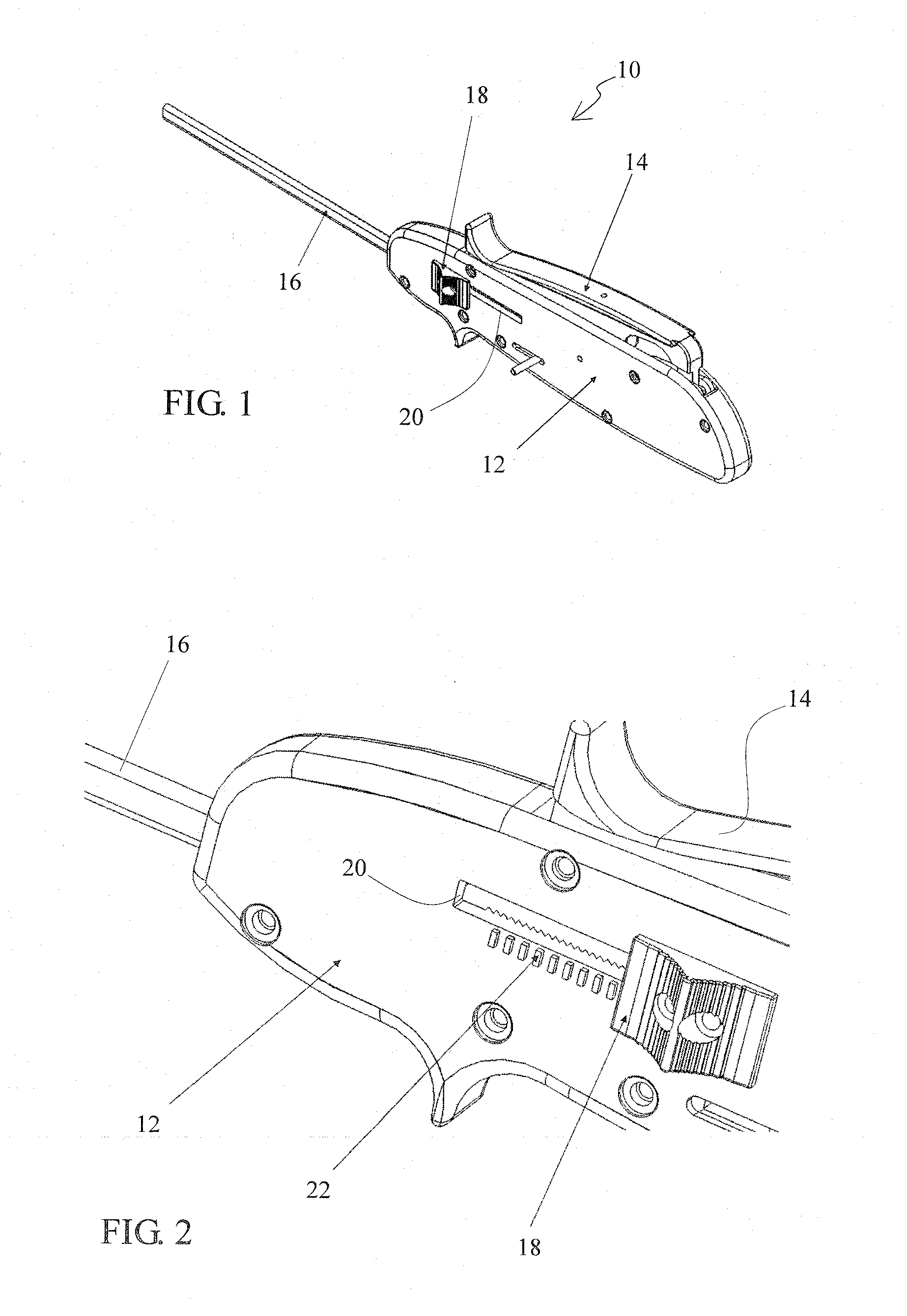
[0038]Referring now more particularly to the drawings, there is shown in FIG. 1 an embodiment of a meniscal repair device 10 constructed in accordance with the principles of the present invention. The device 10 comprises a handle 12 which has a suture needle advancement lever 14. Distally of the handle 12 is provided a depth limiter/insertion sheath 16. A depth limiter/insertion sheath actuation button 18 is disposed on the handle 12.
[0039]Now with reference to FIGS. 2 and 7, in addition to FIG. 1, additional constructional details of the handle 12 are illustrated. As shown particularly in FIG. 2, the depth limiter/insertion sheath actuation button 18 travels axially within a slot 20. A depth gauge 22 is provided for purposes which will be described below. In FIG. 7, wherein the cover of the handle has been removed to reveal the internal construction of the handle 12, it can be seen that a piston retention lever 24 and a catch spring piston 26 are disposed therein.
[0040]In FIGS. 6 and 8, the distal end of the meniscal repair device 10 is illustrated. The distal end of the device 10 comprises a transfer needle 28 and a catch needle 30. A suture needle 32 is extendable from the transfer needle 28, as shown in FIG. 6, for carrying suture 34 toward the catch needle 30 for purposes to be described below. A catch plunger 36 is also provided, as shown in FIG. 8.
[0041]Now, with reference to the drawing figures, a representative procedure which may be performed using the inventive device 10 will be described. As noted above, in FIG. 1 the device 10 is illustrated as it is configured prior to insertion into a patient. Once the practitioner has measured the depth from the needle insertion point to the approximate needle exit point, the device can be inserted into the patient's knee. The sheath 16 is retractable, and covers the transfer needle 28 and catch needle 30 while the device is introduced into the patient, for the purpose of protecting the patient from being injured by the needle points. The device 10 can be inserted into the patient's knee by any suitable means, such as a cannula or other type of introducer channel. Once the device 10 is inserted to the procedural site, the practitioner then retracts the sheath 16 by pulling the sheath actuation button 18 backwards, and lets the sheath stop at the desired depth of penetration, which is indicated by the sliding depth gauge 22 on the handle 12. Another depth gauge 37, with graduated markings corresponding to those on the depth gauge 22, is disposed on the distal end of the catch needle 30, as shown in FIG. 3. This depth gauge is visible arthroscopically during the course of the procedure.
[0042]The practitioner continues to insert the device 10 until the sheath 16 comes into contact with the meniscus 38, at which point the device will be unable to go any deeper. This step of insertion is illustrated in sequential FIGS. 3 and 5. Note that in FIG. 4, distal progress of the device 10 has stopped, because the distal end 39 of the sheath 16 is in contact with the meniscus 38.
[0043]Once the needles 28 and 30 have been fully inserted through the meniscal tear 40 to be repaired, the practitioner then squeezes the suture needle advancement lever 14 downwardly toward the body of the handle 12. This action drives the suture needle 32 from the transfer needle 28 and into the catch needle 30, as shown in FIG. 6. The suture needle 32 exits the transfer needle 28 through a transfer needle window 42 and a distal end 43 of the suture needle 32 enters the catch needle 30 through a first suture catch window 44. As the suture needle 32 continues its travel, the distal end 43 thereof exits the catch needle 30 through a second suture catch window 46. In order to function in the described manner, the suture needle preferably has a needle point or piercing tip, as shown, configured to give it the ability to pierce through the meniscus 38, and is sufficiently flexible so that it can be housed in a straightened configuration inside the transfer needle 28 prior to actuation and then take the necessary bend during deployment. The suture needle 32 can be made of a spring tempered stainless steel or a shape memory type of alloy such as nitinol. It can be manufactured with processes that pre-shape it, thereby allowing it to be advanced out of the transfer needle 28 and into the catch needle 30.
[0044]Once the suture needle advancement lever 14 has been squeezed fully, the catch plunger 36 inside the catch needle 30 is actuated by releasing the catch spring piston 26 in the handle 12. A protrusion 48 on the suture needle advancement lever 14 hits the piston retention lever 24, which releases the catch spring piston 26 (FIG. 7). The catch spring piston 26 drives the catch plunger 36 toward the suture 34 and the suture needle 32. The catch plunger 36 advances distally sufficiently to collide with the suture 34 and pin the suture against the suture needle 32.
[0045]Releasing the suture needle advancement lever 14 retracts the suture needle 32, leaving the suture 34 behind inside of the catch needle 30. Once this step is completed, the device 10 is retracted from the patient. Since the suture 34 entered the patient attached to the transfer needle 28, and has now been passed to the catch needle 30, a suture loop 50, as shown in FIG. 9, has now been created through the meniscus 38.
[0046]At this juncture, a pre-tied knot 52 is pulled tightly against the meniscus 38 and provides fixation for healing of the now closed meniscal tear 40. This pre-tied knot may be initially disposed on the instrument 10, and then slid down the suture legs 34 distally until it contacts the meniscus. The long ends of the suture 34, which extend proximally from the procedural site, are then cut off once the knot 52 is in place. The repaired meniscus 38 is shown in FIG. 10.
[0047]FIGS. 11-13 illustrate three alternative needle embodiments, wherein the transfer needle 28 and the catch needle 30 are curved, rather than straight, as in the embodiment illustrated in FIGS. 1-10. Curves of the type disclosed in FIGS. 11-13 may be used to facilitate maneuvering beneath the femoral condyles.
[0048]Currently, the curves being explored are fixed during the manufacturing process. The cavity between the femoral condyle and the meniscus can be quite tight, and as such, in some embodiments of the invention, it can be advantageous for the curves to be adjusted by the practitioner, as needed, to maneuver inside of the joint space.
[0049]The approach shown in the figures thus far involve a horizontal stitch placement. However, it is possible, and has been achieved by the inventor in cadaver tissue, to rotate the needle into a vertical position and to place the stitch. There are instances where this would be an advantageous approach from a repair strength standpoint.
[0050]The bevel orientation of the needles is currently fixed. However, the bevels can be changed in order to make the device easier to use.
[0051]The shield/depth limiter shown and described above is one approach with regards to limiting the insertion depth of the device into the meniscus.
[0052]Within the scope of the present invention, it is possible to add a tag or barb onto the end of the suture 34, which will provide a good piercing point, as an alternative to the current suture needle approach. A hard feature may also be employed, which makes capture of the suture easier and more resistant to letting go prematurely.
[0053]The device is not presently re-loadable in the operating room. However, in alternative embodiments, the device may be designed to be easily re-loadable.
[0054]The width of the stitch is an important factor in determining the strength of the final repair. Basically, the wider the stitch, the stronger the repair will be. The width of the stitch, in some invention embodiments, is adjustable in the operating room. This way the practitioner is able to determine the best stitch width for the given situation.
[0055]The bevel orientation of the needles is currently fixed. However, these may change in order to make the device easier to use.
[0056]The sheath/depth limiter described and shown is one alternative with regard to limiting the insertion depth of the device into the meniscus. In the present invention, there is a stationary steel component which joins the needles together and holds their orientation. This component can be made to slide along the axis of the needle. By doing this, it can be utilized for depth limitation.
[0057]Other adjustable depth limiting devices may include inflatable structures, absorbing cushions, ball detents, and metal crush sleeves, for examples.
[0058]A different depth limiting approach is to move the needles in and out of a stationary sheath which provides depth limiting. This way, the needles may be completely shrouded upon entering the patient without need for additional insertion sheaths.
[0059]Still another approach is to utilize a method of force feedback to determine whether the needle tips have gotten past the outer surface of the meniscus and into the capsule. FIGS. 14 and 15 illustrate such a method sequentially. A compression force (plunger) element 54 may be placed on the distal end of the shorter transfer needle 28. When the plunger 54 exits the meniscus and enters the capsule, the force on the needle reduces, and the plunger then springs forward and releases a mechanism which drives a depth limiter 56 distally against the meniscus (FIG. 15) and thus prevents further distal penetration of the needles.
[0060]Of course, while the foregoing invention has been disclosed in connection with the repair of meniscal tissue, it will be recognized that the inventive principles are applicable to many other instances wherein it is desired to repair a tear in a portion of soft tissue.
[0061]Accordingly, although an exemplary embodiment and method according to the invention have been shown and described, it is to be understood that all the terms used herein are descriptive rather than limiting, and that many changes, modifications, and substitutions may be made by one having ordinary skill in the art without departing from the spirit and scope of the invention, which is to be limited only in accordance with the following claims.

PUM

no PUM

Description & Claims & Application Information

We can also present the details of the Description, Claims and Application information to help users get a comprehensive understanding of the technical details of the patent, such as background art, summary of invention, brief description of drawings, description of embodiments, and other original content. On the other hand, users can also determine the specific scope of protection of the technology through the list of claims; as well as understand the changes in the life cycle of the technology with the presentation of the patent timeline. Login to view more.

Similar technology patents

Classification and recommendation of technical efficacy words

Why Eureka
Try Eureka