Eureka AIR delivers breakthrough ideas for toughest innovation challenges, trusted by R&D personnel around the world.

System and method for monitoring mechanical seals

a mechanical seal and wear monitoring technology, applied in frequency analysis, special data processing applications, amplifier modifications to reduce noise influence, etc., can solve the problems of limited usefulness of those methods and direct relationship of seal face wear

Active Publication Date: 2010-04-29
HORAK MICHAEL N
View PDF16 Cites 25 Cited by
  • Summary
  • Abstract
  • Description
  • Claims
  • Application Information

AI Technical Summary

Benefits of technology

[0016]It is the primary object of the present invention to provide novel and improved wear monitoring for mechanical seals that will produce an indication that the wear of a seal face reached a level where the seal face should be replaced to prevent a sudden seal failure during operation of the machine in which the mechanical seal is installed.
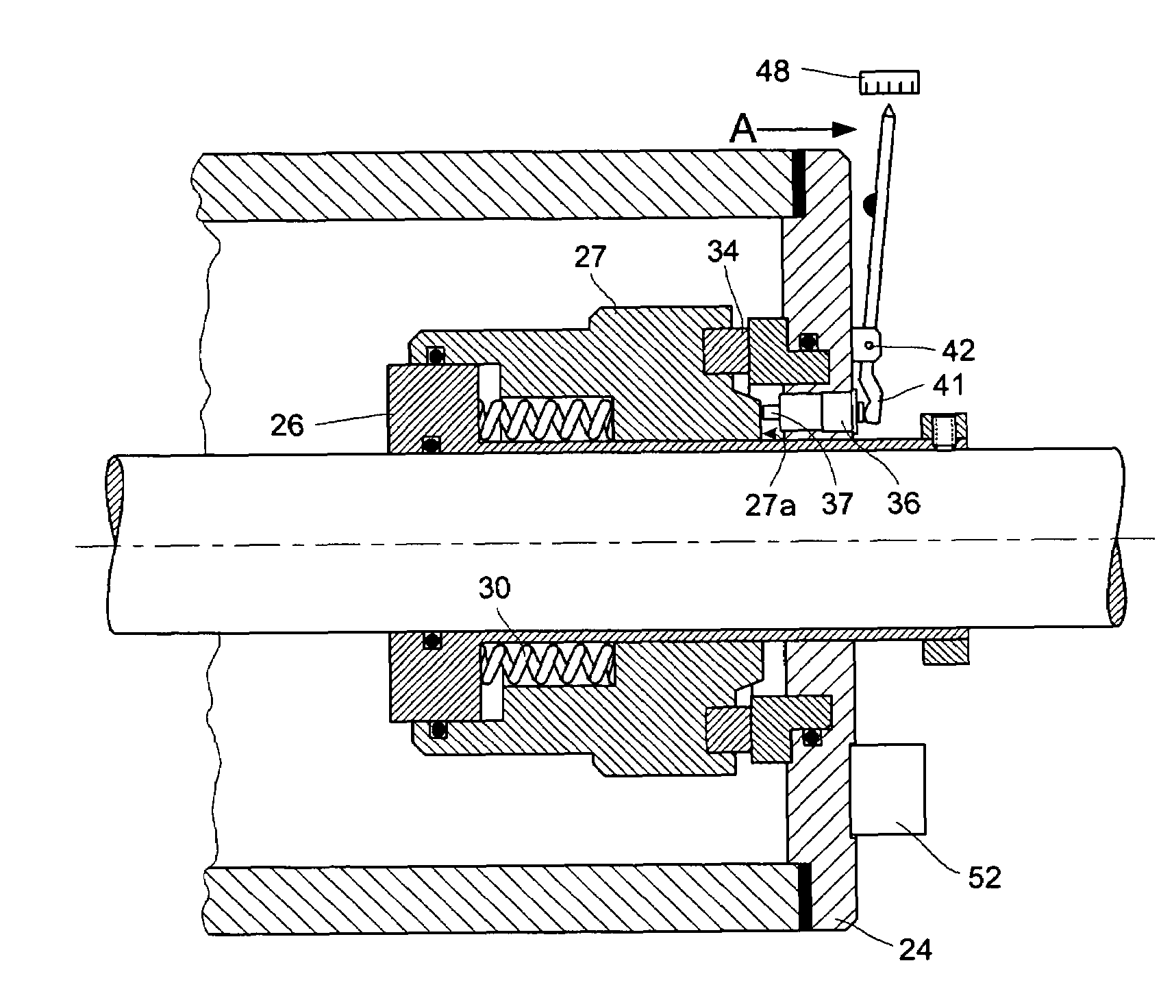
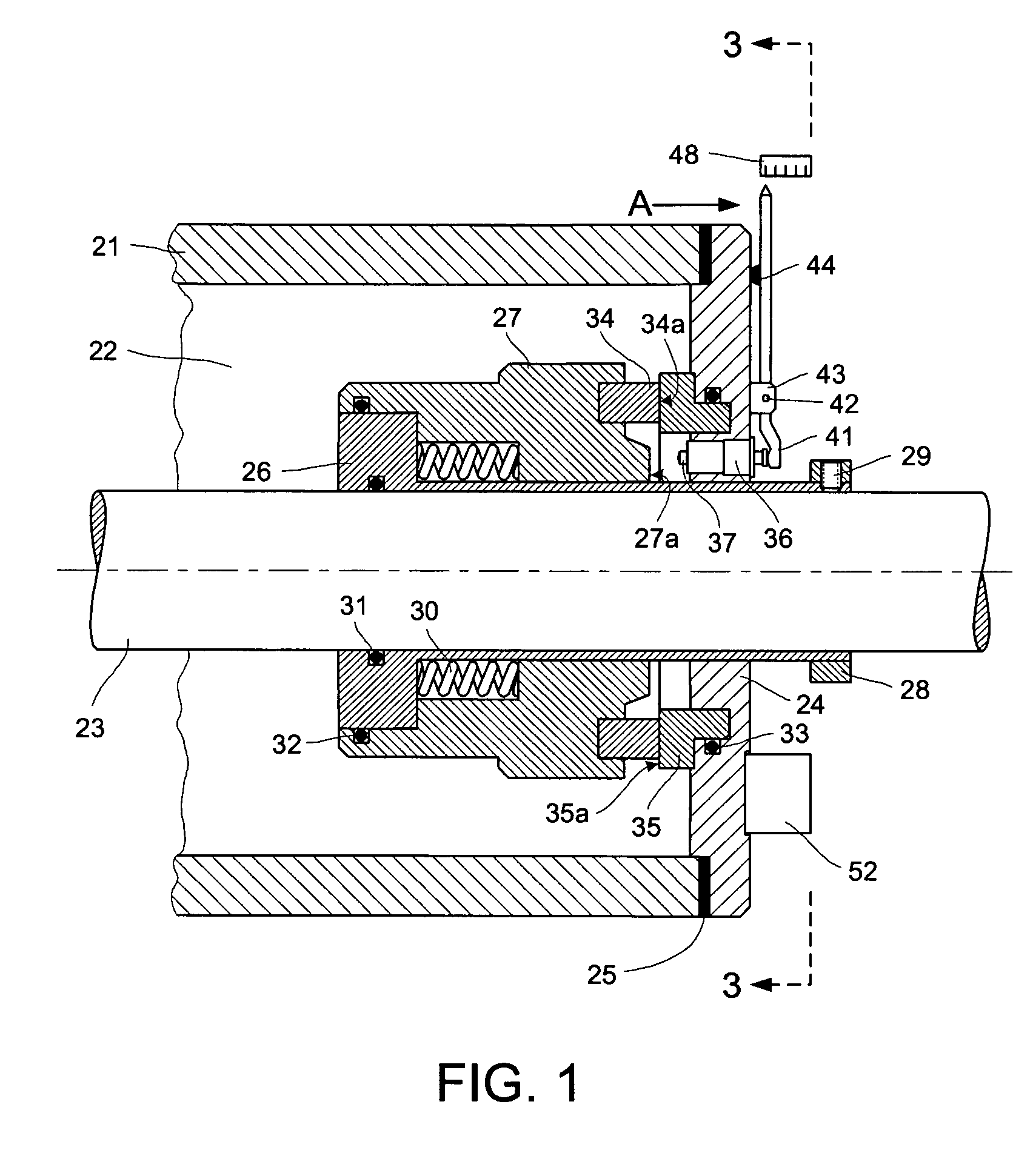
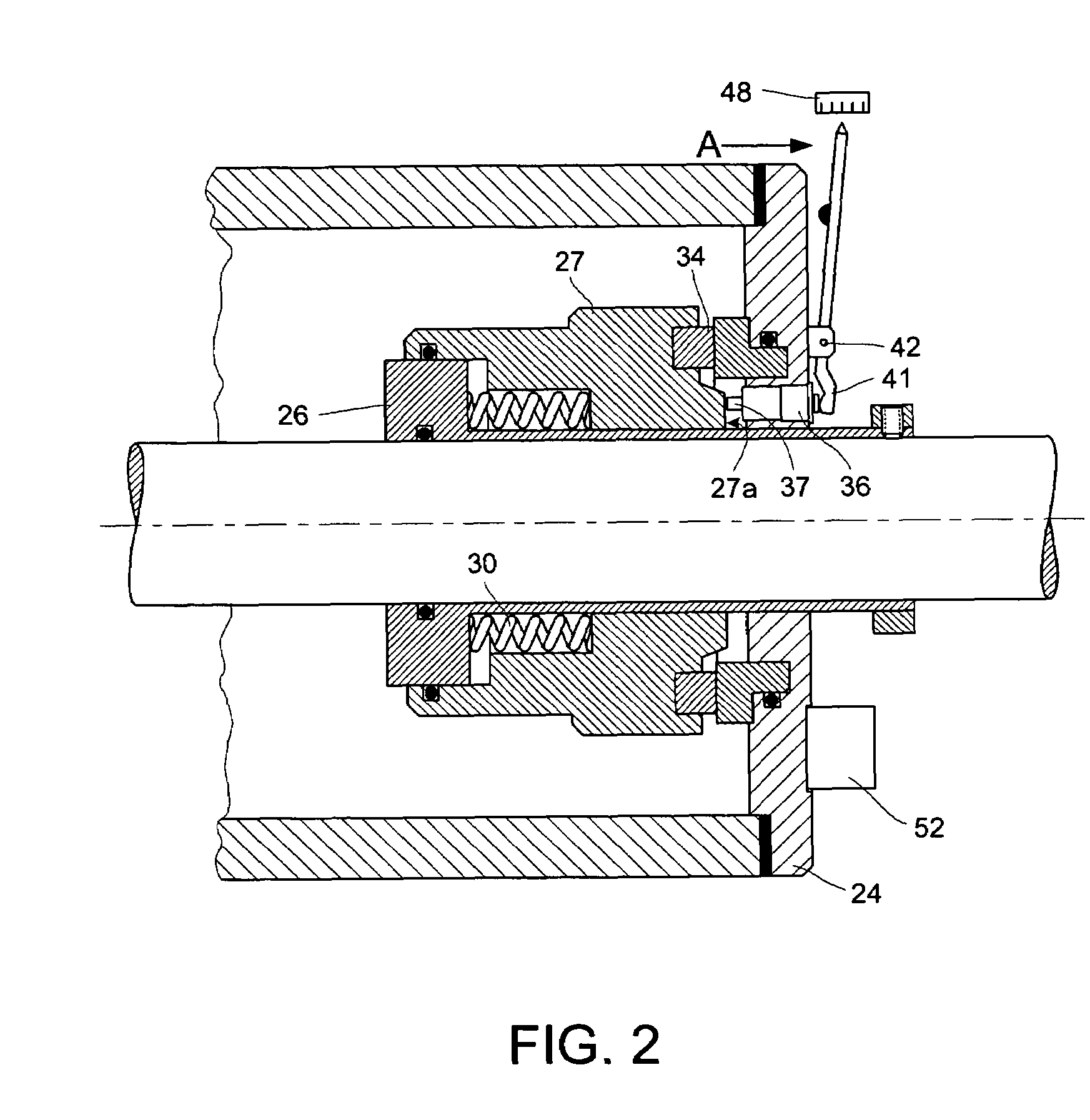
[0017]The detection of the wear in a mechanical seal with a rotating seal face is accomplished with a movable wear probe that, if activated, can move toward the rotating seal face and contact it or a seal component associated with it. The probe is designed to contact the rotating seal component with extremely low force that will not disturb the sealing action of the seal. The contact force can be extremely low because detection of contact is based on detection of stress waves generated at the point of contact. In the development of the present invention, experiments have shown that a wear probe made of soft material and pressed against the rotating seal component with extremely low force generates measurable stress wave signals that can be used for accurate measurement of seal face wear.

Problems solved by technology

Therefore, the level of seal face wear is directly related to the distance that the probe moved to make contact with the component.
The usefulness of those methods is limited by the problems described in detail in the Background of the Invention section.

Method used


Image

  • System and method for monitoring mechanical seals
  • System and method for monitoring mechanical seals
  • System and method for monitoring mechanical seals

Examples


Embodiment Construction

[0035]The preferred forms of the invention will now be described with reference to the accompanying drawings. The appended claims are not limited to the preferred forms and no term and / or phrase used herein is to be given a meaning other than its ordinary meaning unless it is expressly stated otherwise.

[0036]FIG. 1 illustrates a cartridge mechanical seal with rotating seal face 34 and stationary seal seat 35 for providing sealing between stationary machine housing 21 and rotating shaft 23. Cartridge mechanical seals are pre-assembled packages of seal components that make installation and maintenance simple because the entire seal cartridge is handled as a single machine part. Gasket 25 is installed between housing 21 and seal gland 24 to prevent leakage of the fluid sealed in compartment 22 through their interface. Seal seat 35 is mounted in a recess in gland 24 and gland O-ring 33 seals their interface. Cartridge sleeve 26 is attached to shaft 23 with set screws 29 that fit in thre...


PUM


Abstract

A mechanical seal monitoring system and method that measure the wear of seal faces of a mechanical seal where the mechanical seal seals a rotating machine portion from another portion of the machine. The system preferably uses a wear probe movable relative to a rotating seal component so that the wear probe can contact the rotating component. The wear of the seal is preferably determined by the relative movement that is required for the wear probe to contact the rotating component. Preferably, stress waves induced by the rubbing between the probe and the rotating component are detected by a stress-wave sensor, processed by a signal processor, and either displayed to the user numerically or reported to a monitoring computer. A signal intensity comparison method is preferably used to make the detection process insensitive to background noise generated by sources other than the contact of the wear probe and the rotating component.

Description

RELATED PATENT APPLICATIONS[0001]The subject patent application expressly claims priority from U.S. Provisional Patent Application Ser. No. 61 / 108,535 filed on Oct. 26, 2008 under 35 USC §119(e). The entire contents of U.S. Provisional Patent Application Ser. No. 61 / 108,535 are herein incorporated by reference.TECHNICAL FIELD[0002]This invention relates generally to methods and apparatus for monitoring wear of mechanical seals. In its most preferred form, the present invention provides a method and apparatus for providing an early indication of incipient failures of mechanical seals due to wear of their sealing faces.BACKGROUND OF THE INVENTION[0003]Mechanical seals provide sealing between rotating portions of a machine, e.g. a rotating shaft and another portion of the machine, e.g. a stationary machine housing. The sealing action takes place between a seal face and a seal seat, one of which rotates with the shaft while the other is stationary and attached to the machine housing. Th...

Claims


Application Information

Patent Timeline
IPC IPC(8): G01N19/00G06F19/00
CPCG01N29/14F16J15/3492
Inventor HORAK, MICHAEL N.
Owner HORAK MICHAEL N
Why Eureka
Eureka Blog
Learn More