
Vacuum-Insulated Glass Windows With Glass-Bump Spacers

a technology of vacuum insulation glass and glass window, applied in glass making apparatus, manufacturing tools, transportation and packaging, etc., can solve the problems of unsightly windows, cost and complexity of the vig window manufacturing process

Active Publication Date: 2010-05-06
CORNING INC
View PDF15 Cites 49 Cited by
  • Summary
  • Abstract
  • Description
  • Claims
  • Application Information

AI Technical Summary

Benefits of technology

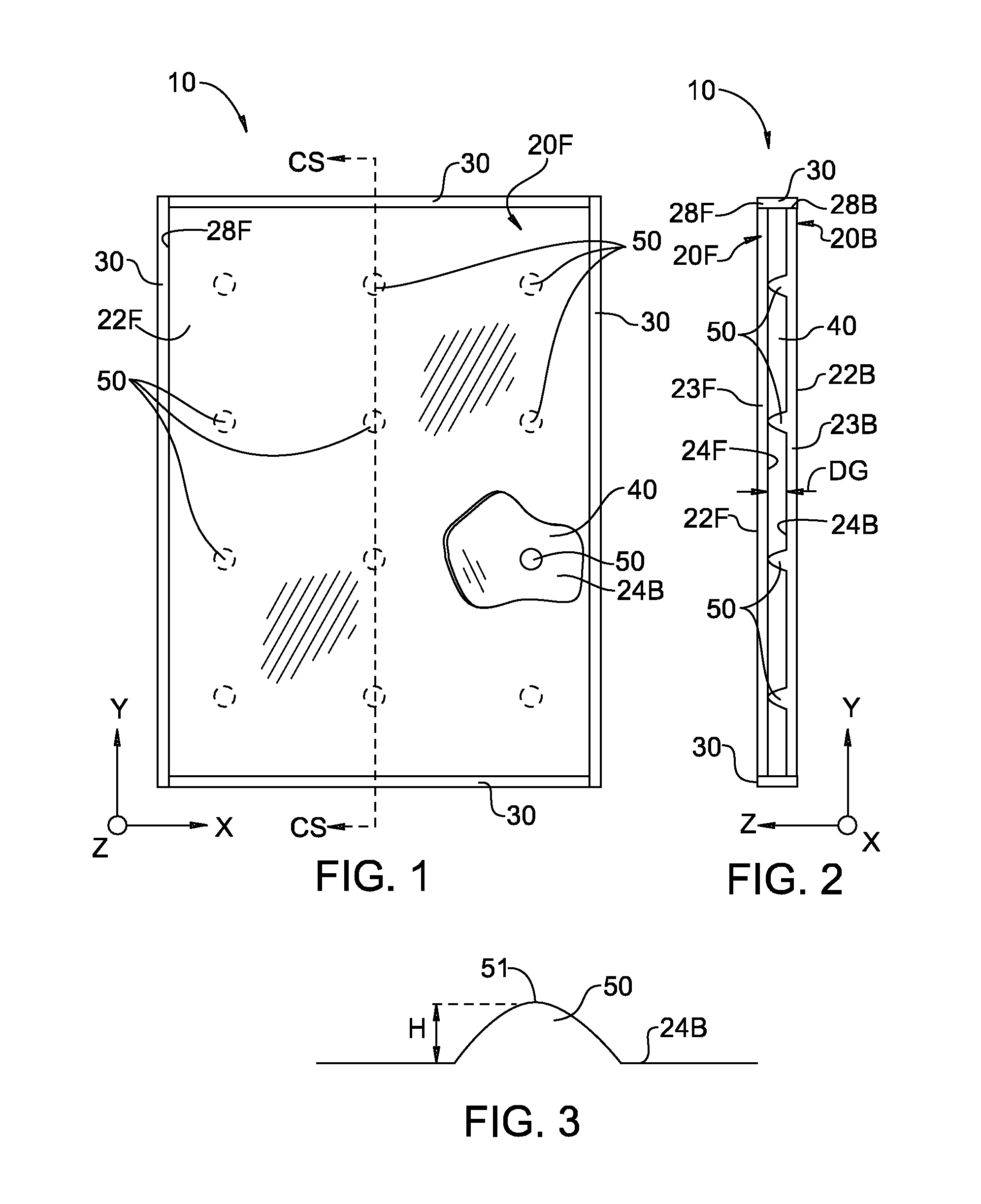
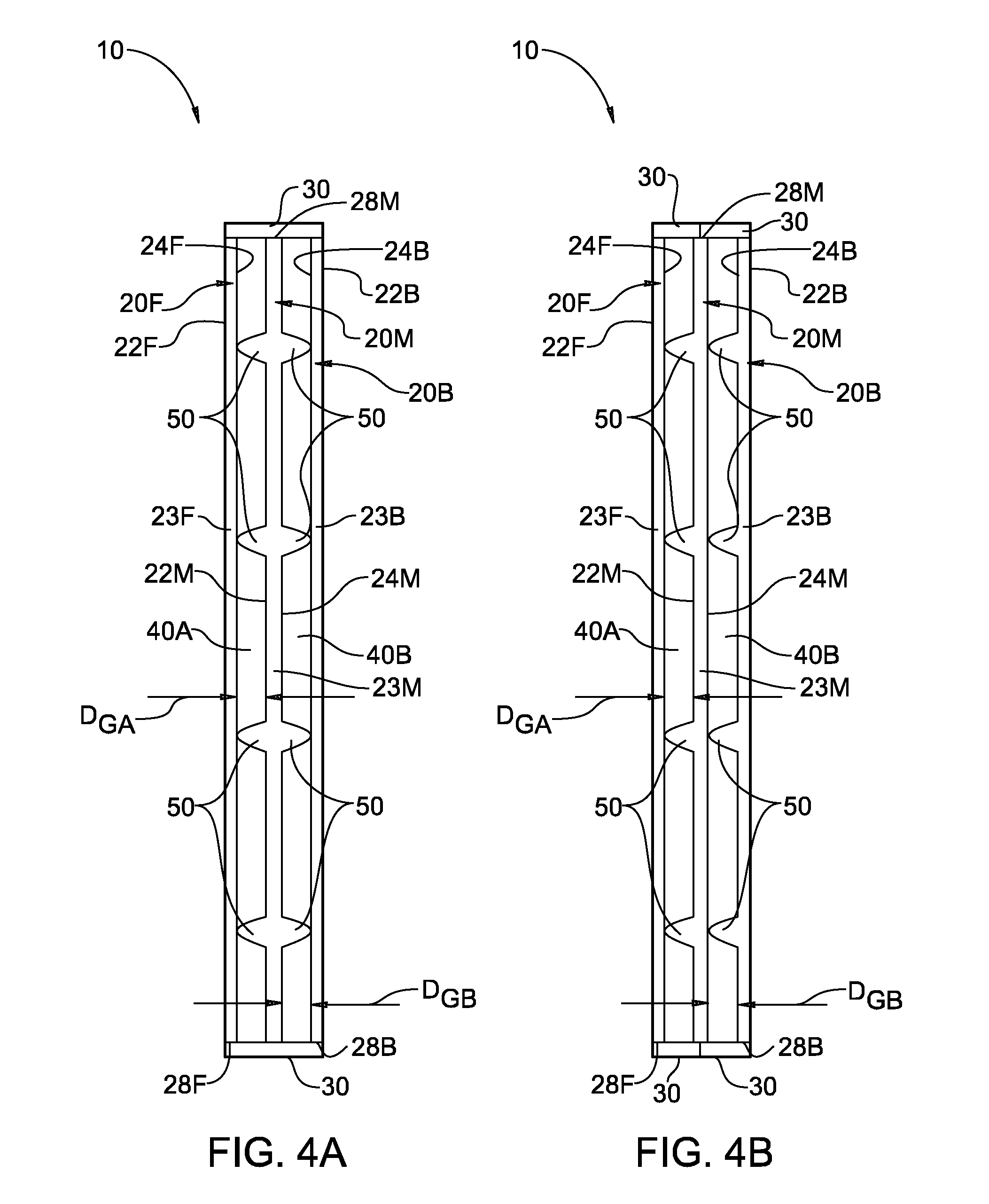
[0004]A first aspect of the present invention is a VIG window. The VIG window includes a first glass pane having a first body formed from a first glass material and having first opposite surfaces and a first outer edge. The VIG window also includes a second glass pane spaced apart from and disposed substantially parallel to the first glass pane at a first distance and having a second body formed from a second glass material and having second opposite surfaces and a second outer edge. A first edge seal is formed around the respective first and second outer edges so as to define a first sealed interior region between the first and second glass panes, wherein the first sealed interior region has a vacuum pressure of less than one atmosphere. The VIG window further includes a first plurality of glass-bump spacers integrally formed with the first glass pane in one of the first surfaces and consisting of the first glass material from the first body portion, and contacting the second glass pane so as to maintain the spaced apart first distance.

Problems solved by technology

While present-day spacers are effective in separating the panes, they tend to be visible when looking through the window, thereby making the window unsightly.
In addition, the need to dispose the discrete spacers between the panes and then fix the spacers to the panes adds cost and complexity to the VIG window manufacturing process.

Method used


Image

  • Vacuum-Insulated Glass Windows With Glass-Bump Spacers
  • Vacuum-Insulated Glass Windows With Glass-Bump Spacers
  • Vacuum-Insulated Glass Windows With Glass-Bump Spacers

Examples


Embodiment Construction

[0023]For purposes of description herein, the terms “front,”“back,”“middle,” and derivatives thereof are relative terms used to facilitate describing the apparatus and methods of the invention. Accordingly, it is to be understood that the invention may assume various alternative orientations and step sequences, except where expressly specified to the contrary. It is also to be understood that the specific devices and processes illustrated in the attached drawings and described in the following specification are embodiments of the inventive concepts defined in the appended claims. Hence, specific dimensions and other physical characteristics relating to the embodiments disclosed herein are not to be considered as limiting, unless the claims expressly state otherwise.

[0024]The term “photo-induced absorption” is broadly understood to mean a local change of the absorption spectrum of a glass pane resulting from locally exposing (irradiating) the glass pane with optical radiation. Photo-...


PUM

PropertyMeasurementUnit
vacuum pressureaaaaaaaaaa
heightaaaaaaaaaa
heightaaaaaaaaaa

Abstract

Vacuum-insulated glass (VIG) windows (10) that employ glass-bump spacers (50) and two or more glass panes (20) are disclosed. The glass-bump spacers are formed in the surface (24) of one of the glass panes (20) and consist of the glass material from the body portion (23) of the glass pane. Thus, the glass-bump spacers are integrally formed in the glass pane, as opposed to being discrete spacer elements that need to be added and fixed to the glass pane. Methods of forming VIG windows are also disclosed. The methods include forming the glass-bump spacers by irradiating a glass pane with a focused beam (112F) from a laser (110). Heating effects in the glass cause the glass to locally expand, thereby forming a glass-bump spacer. The process is repeated at different locations in the glass pane to form an array of glass-bump spacers. A second glass pane is brought into contact with the glass-bump spacers, and the edges (28F, 28B) sealed. The resulting sealed interior region (40) is then evacuated to a vacuum pressure of less than one atmosphere.

Description

FIELD OF THE INVENTION[0001]The present invention relates generally to vacuum-insulated glass windows, and in particular to such windows that employ glass-bump spacers.BACKGROUND ART[0002]Vacuum-insulated glass (VIG) windows typically consist of two or more glass panes with a vacuum in between, which provides improved thermal and noise insulating properties as compared to ordinary glass windows. To prevent sagging of the glass panes, discrete spacers are placed between the glass panes to prevent the panes from contacting each other. The spacers are typically made of aluminum, plastic, ceramic, or glass and are distinct from the glass panes, i.e., they are discrete elements disposed and fixed between the glass panes.[0003]While present-day spacers are effective in separating the panes, they tend to be visible when looking through the window, thereby making the window unsightly. In addition, the need to dispose the discrete spacers between the panes and then fix the spacers to the pan...

Claims


Application Information

Patent Timeline
Patent Type & Authority Applications(United States)
IPC IPC(8): E06B3/663
CPCE06B3/6612E06B3/66304Y02B80/24C03B23/0086Y10T428/24182C03C23/0025Y02A30/25C03B2215/414B23K26/034B23K26/03B23K26/032B23K26/57B23K26/53C03B23/02Y02B80/22Y02A30/249
Inventor GRZYBOWSKI, RICHARD R.HARVEY, DANIEL R.LOGUNOV, STEPHAN LVOVICHRICOULT, DANIEL LOUIS GABRIELSTRELTSOV, ALEXANDER MIKHAILOVICH
Owner CORNING INC
Learn More