Method for incrementally ascertaining a rotation angle of a shaft

a technology of incremental ascertaining and rotation angle, which is applied in the direction of digital computer details, electrical control, instruments, etc., can solve the problems of systematic error in incremental angle determination, inability to reliably determine the absolute position of the crankshaft, and inability to recognize the direction of rotation of the current internal combustion engine sensor, etc., to achieve accurate determination of the absolute rotation angle of the sha

a technology of incremental ascertaining and rotation angle, which is applied in the direction of digital computer details, electrical control, instruments, etc., can solve the problems of systematic error in incremental angle determination, inability to reliably determine the absolute position of the crankshaft, and inability to recognize the direction of rotation of the current internal combustion engine sensor, etc., to achieve accurate determination of the absolute rotation angle of the sha

US20100107747A1Active Publication Date: 2010-05-06ROBERT BOSCH GMBH

Image

  • Method for incrementally ascertaining a rotation angle of a shaft
  • Method for incrementally ascertaining a rotation angle of a shaft
  • Method for incrementally ascertaining a rotation angle of a shaft

Examples


Embodiment Construction

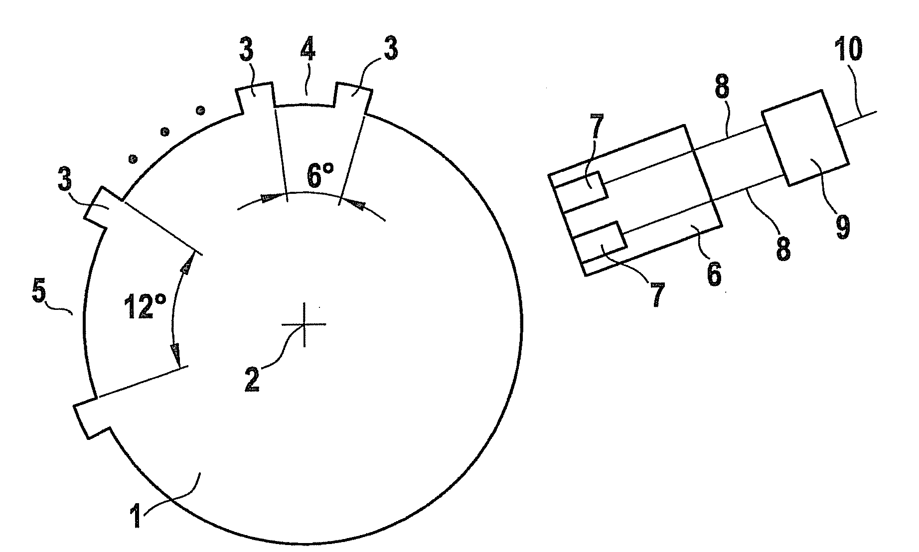
[0018]FIG. 1 shows a schematic drawing of a conventional sensor wheel 1, which is connected to a crankshaft of an internal combustion engine, not depicted here, and rotates about an axis 2 at a rotation of the crankshaft. Sensor wheel 1 has sensor wheel marks (markings), which are formed by an alternating arrangement of teeth 3 and tooth gaps 4. The distance between consecutive pairs of teeth 3 and tooth gaps 4 is 6°. Teeth 3 and tooth gaps 4 may extend over a same angular range of 3°, but they may also be pitched unevenly, for example, by a tooth 3 covering an angular range of 2° and a tooth gap 4 covering an angular range of 4°. A sensor wheel gap 5 is formed by omitting one tooth 3, thus forming a sensor wheel gap 5 having an angle of 12°.

[0019]A sensor 6 is associated with sensor wheel 1. Sensor 6 includes two sensor elements 7, which may be Hall elements, inductive sensors, or the like, for example. Sensor elements 7 deliver electrical signals via signal lines 8, from which a d...


PUM


Abstract

A method for incrementally ascertaining a rotation angle of a shaft, in particular of a crankshaft of an internal combustion engine, the shaft being connected to a sensor wheel having teeth and tooth gaps, and at least one sensor being associated with the sensor wheel, the sensor generating a square-wave signal as an output signal which may assume a first value or a second value, and a signal edge being associated with a tooth edge, and the position in time of a counteredge with respect to the edge encoding a direction of rotation, an assignment of a direction of rotation reversal point to a tooth of the sensor wheel or a tooth gap of the sensor wheel being encoded by the position in time of the counteredge with respect to the edge, the rotation angle being ascertained by adding an increment for each signal edge to a counter, after a direction of rotation reversal while a tooth passes the sensor, a half-increment, having a sign of the direction of rotation after the direction of rotation reversal, being incremented once and in the event of a direction of rotation reversal while a tooth gap passes the sensor, a half-increment, having a sign of the direction of rotation prior to the direction of rotation reversal, being incremented once.

Description

FIELD OF THE INVENTION[0001]The present invention relates to a method for incrementally ascertaining a rotation angle of a shaft, a method for encoding an output signal of a sensor, a sensor for a device for determining a rotation angle of a shaft, and a computer program for performing one of the above-mentioned methods.BACKGROUND INFORMATION[0002]Determining the crankshaft angle is one of the central tasks for controlling internal combustion engines. Conventional approaches use incremental sensors on the crankshaft and the camshaft. The typical sensor wheels having increment marks make cooperation of the crankshaft and camshaft sensors possible for determining the crankshaft angle. Another improvement on the control of an internal combustion engine is achieved if the crankshaft position is detected accurately when the internal combustion engine is stopped. This makes it possible to considerably speed up the restart of the internal combustion engine and to achieve a positive effect ...

Claims


Application Information

Patent Timeline
06 May 2010
Publication
US20100107747A1
IPC
G01M15/00
CPC
F02D41/009; G01P13/045; G01D5/24476
Inventors
ROLEW, EDUARD; KASSNER, UWE