Shifting device for an automatic transmission

Inactive Publication Date: 2010-05-06
DR ING H C F PORSCHE AG
View PDF10 Cites 9 Cited by
  • Summary
  • Abstract
  • Description
  • Claims
  • Application Information

AI Technical Summary

Benefits of technology

[0012]In accordance with an advantageous embodiment, the release button can realize the two actuation positions by means of different actuating pressures and/or actuation distances, where the actuating pressure and/or the actuation distance for activating the second actuation position is/are greater that that/those for activating the first actuation position. This means that, after actuation of the release button, the second actuation position can be reached by pressing or moving the release button beyond the first actuation position. The driver therefore realizes intuitively that the shifting device will first allow him initially to shift into Reverse and that he can shift into Park only by pushing the release button down even farther.
[0013]In an especially advantageous embodiment, the release button can be moved out of its unactuated, resting position by pressing it against an initial resistance, where this initial resistance forms a pressure stage, and when this is overcome, the release button snaps into the second actuation position and then can be held there by pressing against a holding resistance, which is weaker than the initial resistance. As a result of this design, the user can reach the first actuation position very easily and intuitively, where the snapping effect makes it possible for him to verify the process haptically. The reduced holding force in the first actuation position facilitates frequent shifting between the Reverse, Normal, and Drive, which makes it much easier to maneuver the vehicle, for example.
[0014]In an elaboration, it can be provided that the release button can be moved out of its first actuation position into the second actuation position by pressing it down against an actuation resistance which is greater than

Problems solved by technology

As a result, the unintentional actuation of the release button by the driver will not have the effect of engaging reverse gear while the vehicle is traveling forward.
Maneuvering becomes extremely inconvenient as a result of this measure, however, because the release button must be actuated twice each time it is desired to drive in reverse.
In th

Method used


Image

  • Shifting device for an automatic transmission
  • Shifting device for an automatic transmission
  • Shifting device for an automatic transmission

Examples


Embodiment Construction

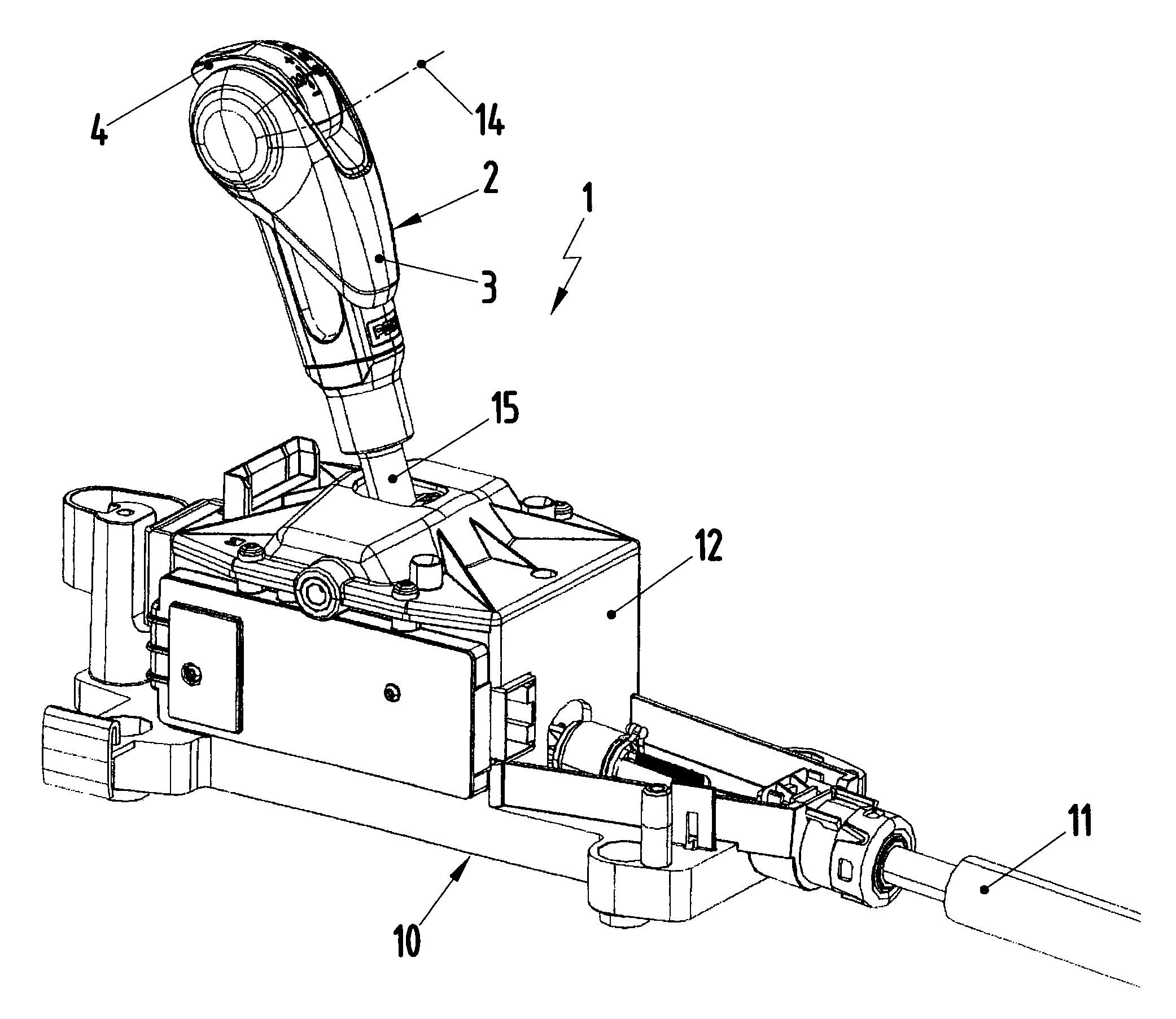
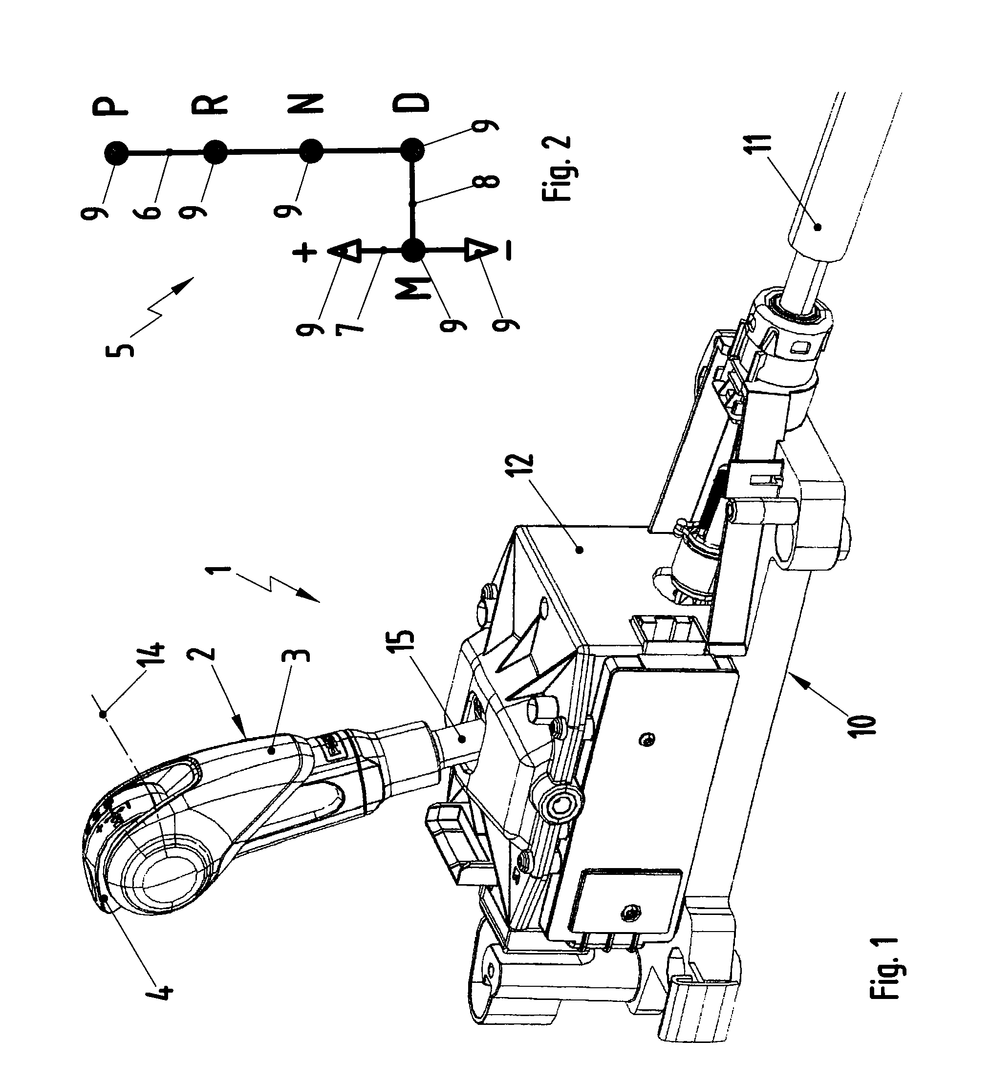
[0022]As shown in FIG. 1, an inventive shifting device 1, which is used in conjunction with an automatic transmission of a motor vehicle, comprises a gear-shift lever 2, which comprises a hand grip 3. A release button 4, which, in this example, is integrated into the hand grip 3, is also provided on the gear-shift lever 2. The gear-shift lever 2 can be moved in a shift gate 5, a simplified view of which is shown in FIG. 2. The shift gate 5 comprises an automatic shift track 6, a manual shift track 7, and a transverse track 8 The gear-shift lever 2 can be moved in the automatic shift track 6 and in the manual shift track 7 to select gear-shift positions 9. For example, the automatic shift track 6 comprises the following gear-gear-shift positions: Park P, Reverse R, Neutral N, and Drive D. In contrast, the manual shift track 7 comprises, for example, a Middle M position, an upshift position +, and a downshift position −. The transverse shift track 8 allows the gear-shift lever 2 to be...


PUM


Abstract

A shifting device for an automatic transmission including a locking mechanism which can be moved at least between a locked state and a released state, comprises a release button for changing the state of the locking mechanism, prevents the gear-shift lever from being moved at least into the Park and Reverse positions and at least out of the Park position in a locked state, and allows the gear-shift lever to be moved at least between the positions Park, Reverse, Neutral, and Drive in a release state. The locking mechanism can be converted to a partially released state, in which the gear-shift lever can be moved into and out of the Reverse position, whereas the movement of the gear-shift lever into the Park position remains blocked.

Description

CROSS REFERENCE TO RELATED APPLICATIONS[0001]This U.S. patent application claims priority to German Application DE 10 2008 022 551.7, filed Apr. 30, 2008, which is incorporated by reference herein in its entiretyFIELD OF THE INVENTION[0002]The present invention pertains to a shifting device for an automatic transmission of a motor vehicle.BACKGROUND OF THE INVENTION[0003]A shifting device for an automatic transmission of a motor vehicle which comprises a gear-shift lever, which can be moved in an automatic shift track to select gear-shift positions, is known from DE 100 57 299 A1. This automatic shift track can comprise, for example, gear-shift positions for parking, reverse, neutral, and drive. The known shifting device also comprises a locking mechanism, which can be switched at least between a locked state and a released state. It also comprises a release button for changing the state of the locking mechanism. In the locked state, the locking mechanism blocks the movement of the ...

Claims


Application Information

Patent Timeline
IPC IPC(8): G05G5/02
CPCF16H59/0204F16H59/10F16H61/22F16H2059/0282Y10T74/20098B60K20/00F16H59/12
Inventor SICKART, MICHAEL
Owner DR ING H C F PORSCHE AG
Why Eureka
Try Eureka