Multi-directional submersible floating aerator

a multi-directional, floating aerator technology, applied in the field of aerators, can solve the problems of low oxygen aeration efficiency, low aeration efficiency, and many problems of conventional submersible floating aerators, and achieve the effect of improving aeration efficiency and being more even and stabl

Active Publication Date: 2010-05-06
SUN SHULIN +1
View PDF25 Cites 6 Cited by
  • Summary
  • Abstract
  • Description
  • Claims
  • Application Information

AI Technical Summary

Benefits of technology

[0023]Advantages of the invention include the following: since the multi-directional seat is used for evenly distributing compressed air, and an axial hole of a hollow transmission shaft of the submersible hollow shaft motor sprays and spreads air to the surrounding of the multi-directional submersible floating aerator, aeration is more even and stable, and aeration efficiency is greatly improved.

Problems solved by technology

However, several problems with conventional submersible floating aerators still remain unsolved.
Among these are: great eccentric vibration occurring during operation, aeration is not even, aeration efficiency and oxygen aeration efficiency is low, and there is dead space during oxygen aeration.

Method used


Image

  • Multi-directional submersible floating aerator
  • Multi-directional submersible floating aerator
  • Multi-directional submersible floating aerator

Examples


Embodiment Construction

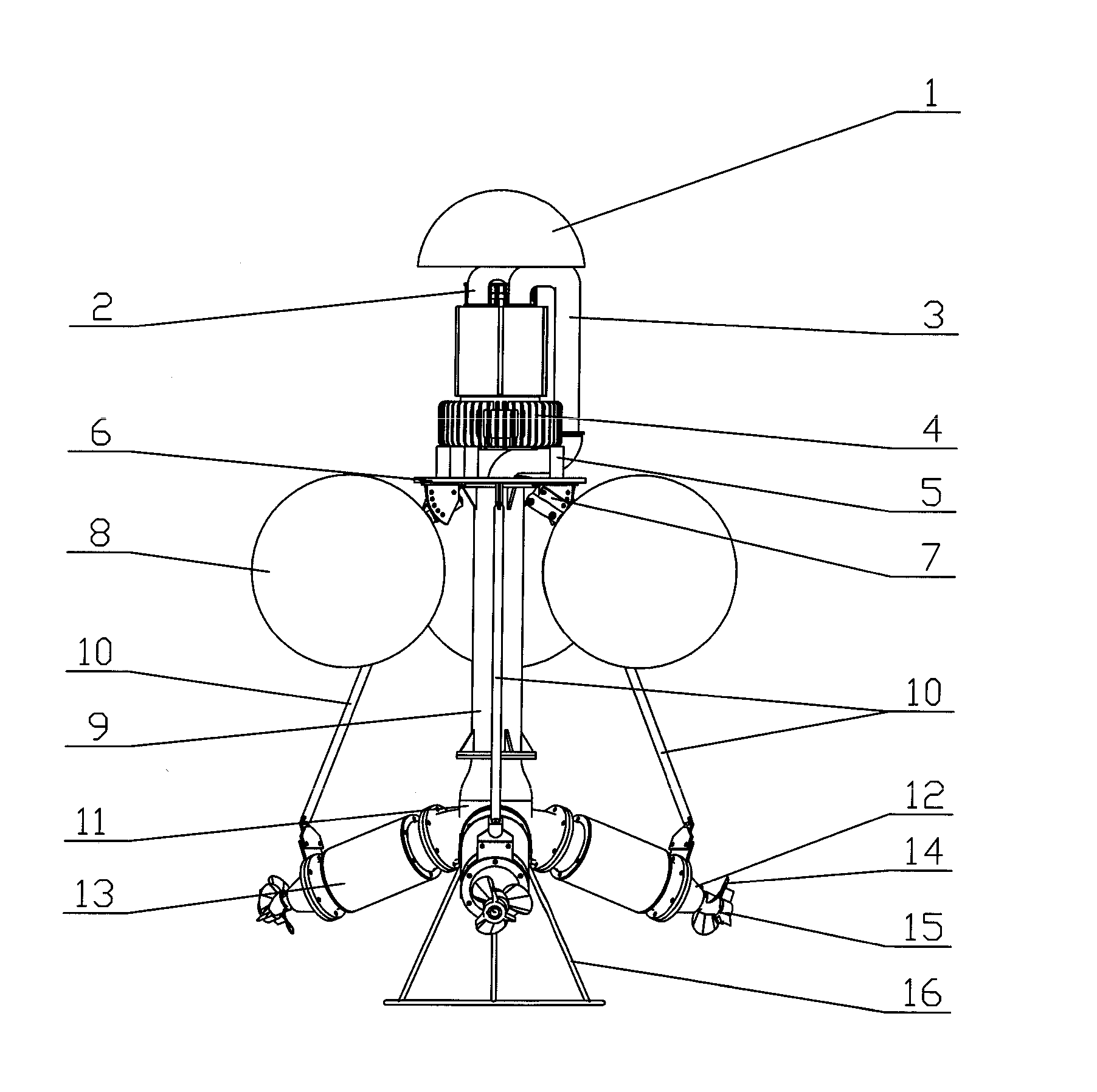
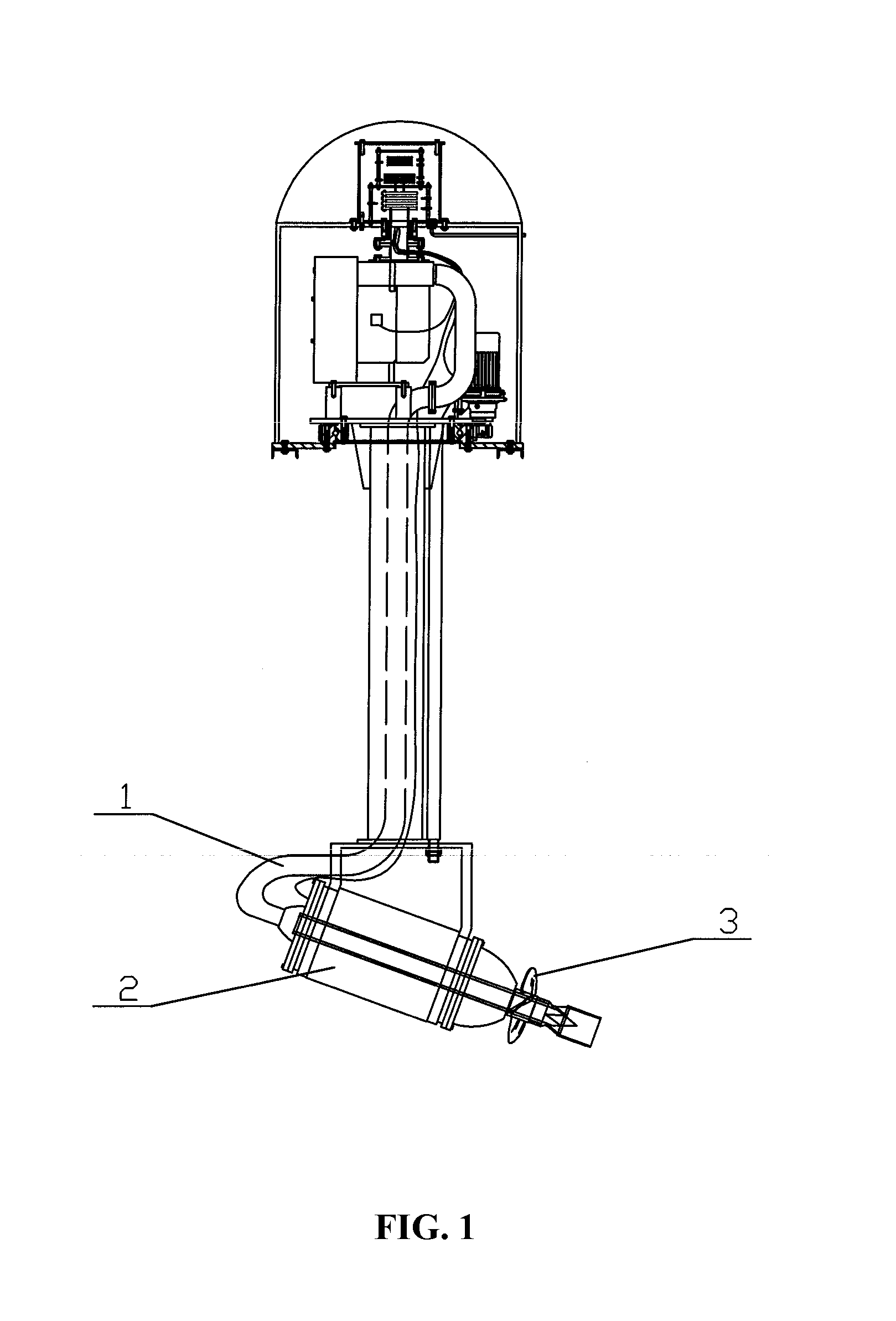
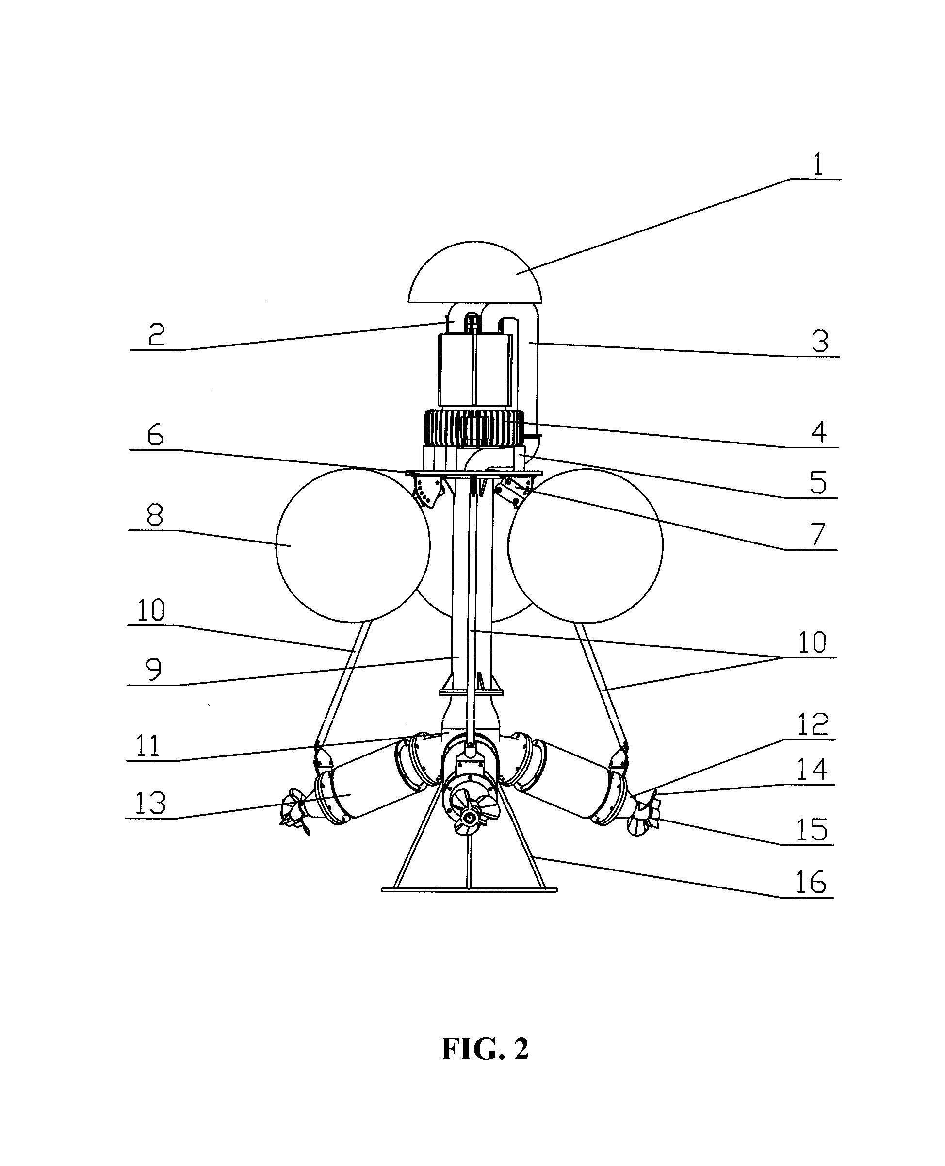
[0034]As shown in FIGS. 2-5, a multi-direction submersible floating aerator of the invention comprises a rain cover 1, an air inlet pipe 2, a compressed air pipe 3, a gas-ring compressor 4, a bracket 5, a base 6, a floating ball 8, a gas inlet tube 9, multiple pull rods 10, a seat 11, a dome 12, multiple submersible hollow shaft motors 13, multiple propellers 14, and a second support 16.

[0035]The rain cover 1 is disposed above the gas-ring compressor 4.

[0036]The air inlet pipe 2 is connected to the gas-ring compressor 4.

[0037]The compressed air pipe 3 is connected between the gas-ring compressor 4 and the gas inlet tube 9.

[0038]The gas-ring compressor 4 is connected to the base 6 via bracket 5.

[0039]The base 6 is disposed between the gas-ring compressor 4 and the gas inlet tube 9.

[0040]The floating ball 8 is connected to the bottom of the base 6 via first support 7.

[0041]A top portion of the pull rod 10 is connected to the bottom of the base 6, and a bottom portion of the pull rod 1...


PUM

PropertyMeasurementUnit
forcesaaaaaaaaaa
concentrationaaaaaaaaaa
velocityaaaaaaaaaa

Abstract

A multi-direction submersible floating aerator has a gas-ring compressor (4), a base (6), a gas inlet tube (9), a seat (11), multiple submersible hollow shaft motors (13), and multiple propellers (14). The base (6) is disposed between the gas-ring compressor (4) and the gas inlet tube (9). The propeller (14) is coaxially connected to the submersible hollow shaft motor (13). The seat (11) is disposed between the gas inlet tube (9) and the submersible hollow shaft motor (13). The seat (11) is hollow. A first opening is disposed at the top of the seat (11), and multiple second openings are disposed on one side of the seat (11). The seat is (11) used for evenly distributing compressed air. Thus, the aeration is more even and stable, and aeration efficiency is greatly improved.

Description

CROSS-REFERENCE TO RELATED APPLICATIONS[0001]This application is a continuation-in-part of U.S. application Ser. No. 11 / 953,093 filed on Dec. 10, 2007, which claims priority to Chinese Patent Application No. 200610168196.0 filed on Dec. 15, 2006. This application is also a continuation-in-part of U.S. application Ser. No. 12 / 144,625 filed on Jun. 24, 2008, which claims priority to Chinese Patent Application No. 200810089642.8 filed on Apr. 9, 2008. Pursuant to 35 U.S.C. §119 and the Paris Convention Treaty, this application further claims the benefit of Chinese Patent Application No. 200910160936.X filed on Jul. 31, 2009. The contents of all of the aforementioned national and foreign applications are incorporated herein by reference in their entirety.BACKGROUND OF THE INVENTION[0002]1. Field of the Invention[0003]The invention relates to an aerator, and more particularly to a multi-directional submersible floating aerator.[0004]2. Description of the Related Art[0005]Nowadays submers...

Claims


Application Information

Patent Timeline
Patent Type & Authority Applications(United States)
IPC IPC(8): C02F1/74B01F3/04B01D47/16
CPCB01F3/04539B01F3/04588B01F7/00341B01F7/00733B01F13/0049B01F2003/04546B01F2003/04723C02F3/205Y02W10/15Y02W10/10B01F23/2332B01F23/23311B01F23/23367B01F23/2331B01F27/113B01F27/25B01F33/503
Inventor SUN, SHULINSUN, JIAN
Owner SUN SHULIN
Why Eureka
Try Eureka