Switching power supply apparatus

a power supply and power supply technology, applied in electrical energy, process and machine control, instruments, etc., can solve the problems of low switching noise, large stress on the inductor and diode, and difficult to apply the critical conduction mode control method to the us

Active Publication Date: 2010-05-06
FUJI ELECTRIC CO LTD
View PDF4 Cites 12 Cited by
  • Summary
  • Abstract
  • Description
  • Claims
  • Application Information

AI Technical Summary

Benefits of technology

[0044]the second threshold signal generator circuit sets a voltage dividing ratio of the second threshold signal to the first threshold signal to be smaller than a switching frequency indicated by th...

Problems solved by technology

Since the switching device conducts switching when the inductor current is 0 in the critical conduction mode control method generally, the switching noise caused is low.
However, since a large current ripple is caused in the critical conduction mode control method, a large stress is exerted to the inductor and the diode.
Therefore, it is hard to apply the critical conduction mode control method to the use, in which the load is heavy.
If the OFF-period i...

Method used


Image

  • Switching power supply apparatus
  • Switching power supply apparatus
  • Switching power supply apparatus

Examples


Embodiment Construction

[0059]Now the invention will be described in detail hereinafter with reference to the accompanied drawings which illustrate the preferred embodiments of the invention.

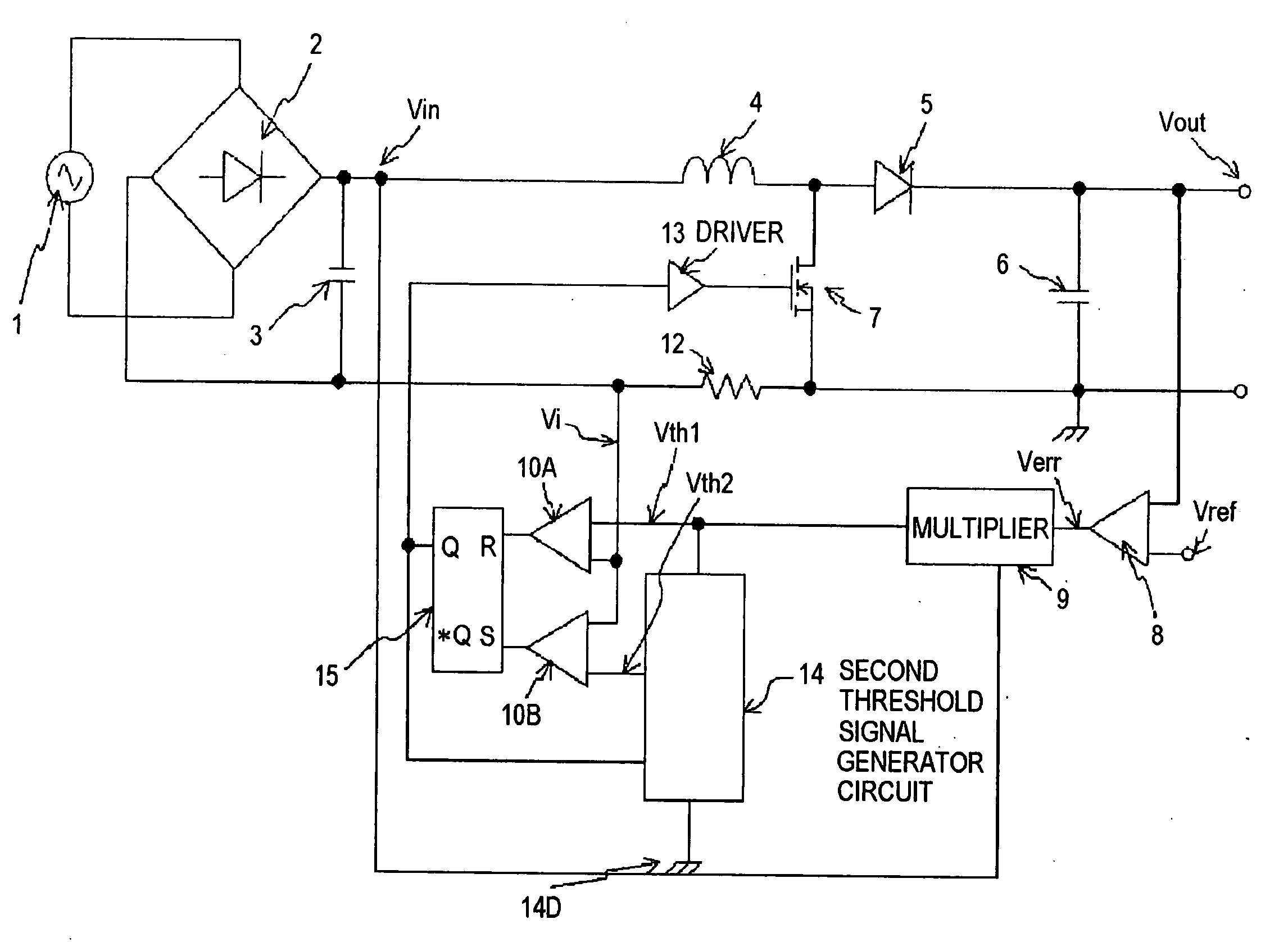
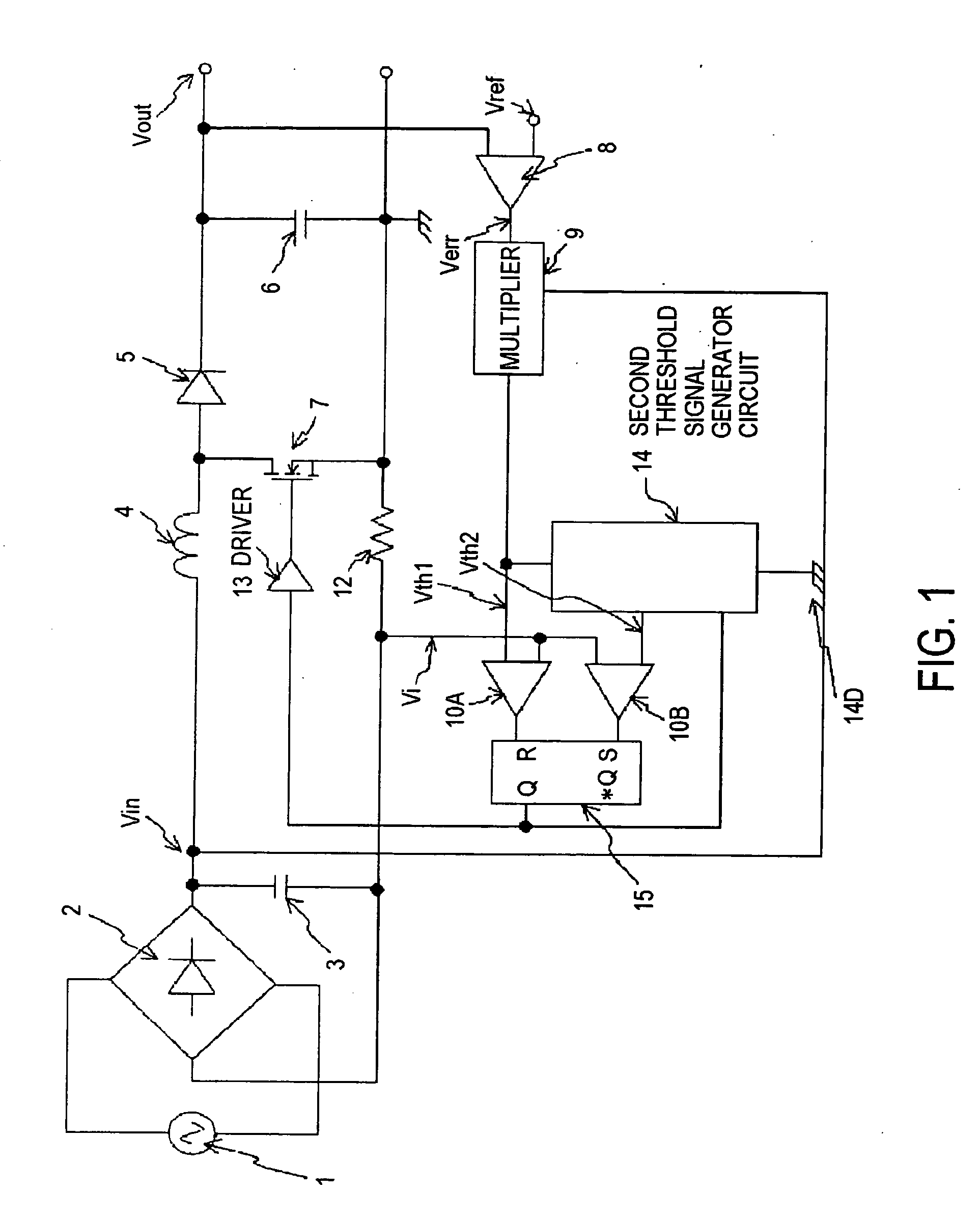
[0060]FIG. 1 is a block circuit diagram showing the configuration of a switching power supply apparatus according to an embodiment of the invention. In FIG. 1, the same reference numerals as used in FIG. 6 are used to designate the same constituent elements and their duplicated description are omitted for the sake of simplicity.

[0061]The output voltage from AC power supply 1 is full-wave-rectified by rectifier circuit 2 formed of a diode bridge and high frequency noises are removed by capacitor 3. A current is fed to capacitor 6 via inductor 4 and diode 5 and smoothed DC voltage Vout is outputted. The one end of switching device 7 such as a MOSFET is connected between inductor 4 and diode 5. As switching device 7 is turned on and the inductor current from inductor 4 flows through switching device 7, the inductor curren...


PUM


Abstract

In a switching power supply apparatus, multiplier 9 multiplies error voltage Verr generated in voltage error amplifier 8 and input voltage Vin to generate first threshold signal Vth1 in-phase with and similar to input voltage Vin and having an amplitude proportional to error voltage Verr. Second threshold signal generator circuit 14 generates second threshold signal Vth2 from first threshold signal Vth1. Switching device 7 is turned on and off so that the inductor current may change between first and second threshold signals Vth1 and Vth2. The switching frequency is detected and the proportional factor of first and second threshold signals Vth1 and Vth2 is changed to control the average switching frequency almost at a constant value for reducing the high frequency noises and the switching losses. The switching power supply apparatus facilitates reducing the noises and losses, improving the power factor thereof, and preventing the response performances thereof from being impaired.

Description

FIELD OF THE INVENTION[0001]The present invention relates to switching power supply apparatuses of a power-factor-improving-type that obtain a stable DC power supply from an AC power supply and make a chopper circuit operate such that the input voltage and the input current thereof are almost in-phase with and similar to each other.BACKGROUND[0002]The control methods for controlling the power-factor-improving-type switching power supply apparatuses include a critical conduction mode control method and a continuous conduction mode control method. In the critical conduction mode control method, a switching device is turned on as the inductor current becomes 0. In the continuous conduction mode control method, the inductor current is controlled so as not to be 0.[0003]Since the switching device conducts switching when the inductor current is 0 in the critical conduction mode control method generally, the switching noise caused is low. Therefore, the critical conduction mode control met...

Claims


Application Information

Patent Timeline
IPC IPC(8): H02M7/155
CPCH02M1/4225Y02B70/126Y02P80/112Y02B70/10Y02P80/10
Inventor SHIMIZU, HIDEO
Owner FUJI ELECTRIC CO LTD
Why Eureka
Try Eureka