Apparatus, imaging device and method for counting x-ray photons
Inactive Publication Date: 2010-05-06
KONINKLIJKE PHILIPS ELECTRONICS NV
View PDF2 Cites 7 Cited by
Summary
Abstract
Description
Claims
Application Information
AI Technical Summary
This helps you quickly interpret patents by identifying the three key elements:
Problems solved by technology
Method used
Benefits of technology
Benefits of technology
[0010]According to one aspect of the invention this is achieved by an apparatus for counting X-ray photons, in particular photons in a computer tomograph, comprising an arrangement adapted to convert impinging photons into countable events and having at least a first photon-sensitive element and a second photon-sensitive element, the apparatus further comprising an output adapted to provide information regarding the number of photons counted, at least a first integrator being coupled to the first photon-sensitive element and a second integrator being coupled to the second photon-sensitive element, further comprising a first summing unit for summing the output of the first and second integrators, the first summing unit being coupled to a feedback device providing a result signal to the output, the result signal further being provided to the first summing unit and to the first and second integrators, so that a total information density generated by the impinging photons arrives as a reduced information density at the output.
[0040]The first and second integrators (digital registers) count any event representing an impinging photon regardless of the time when the event has occurred. The values of the integrators are read out in intervals determined by a clock cycle, and the first summing unit performs a summing action according to the clock cycle. The feedback device receives synchronous data and can be operated in synchronous mode. Therefore, this embodiment provides a simple yet effective means when having to bring the randomly distributed event caused by the photons into a format basing on a clock-cycle.
Problems solved by technology
However, attempting to accurately count the impinging photons, is accompanied by several issues.
One of the issues stems from the random distribution of the photons (Poisson distribution) in time.
This can lead to a situation, where within the time window required to process a single photon a second photon arrives and interferes with the processing of the first photon, thereby leading to incorrect results.
This means that pile-up events occur with a significant likelihood and thus cannot be ignored.
However, this has led to another issue: If a pixel having an active surface of 1 mm×1 mm is replaced by 16 pixels with an area of 250 μm×250 μm the number of information channels increases by a factor of 16 which leads to a 16-fold increase in the information that has to be processed, requiring a significant effort to process and analyze this information.
Method used
Image
Click on the blue label to locate the original text in one second.
Reading with bidirectional positioning of images and text.
Examples
first embodiment
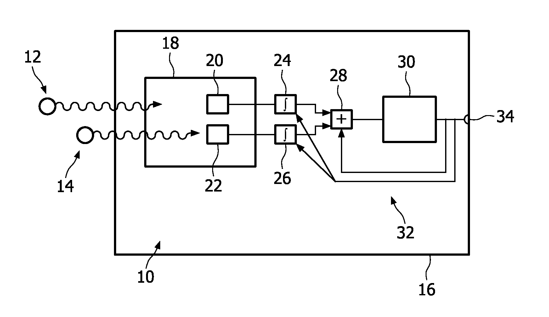
[0048]FIG. 1 shows an apparatus 10 for counting X-ray photons 12, 14 in an imaging device 16, in particular embodied as a computer tomograph. The apparatus 10 comprises an arrangement 18 adapted to convert impinging photons 12, 14 into countable events.
[0049]The arrangement 18 has at least a first photon-sensitive element 20 and a second photon-sensitive element 22. The first and second photon-sensitive elements 20, 22 are coupled to first and second integrators 24, 26 respectively. It should be noted that the lines between the first and second photon-sensitive elements 20, 22 and the first and second integrators 24, 26 are not to be understood as a direct connection, since additional circuitry (not shown) well-known in the art is required to convert impinging photons into countable events.
[0050]A first summing unit 28 is provided for summing the output of the first and second integrators 24, 26 and also a result signal as will be described next.
[0051]The first summing unit 28 is co...
second embodiment
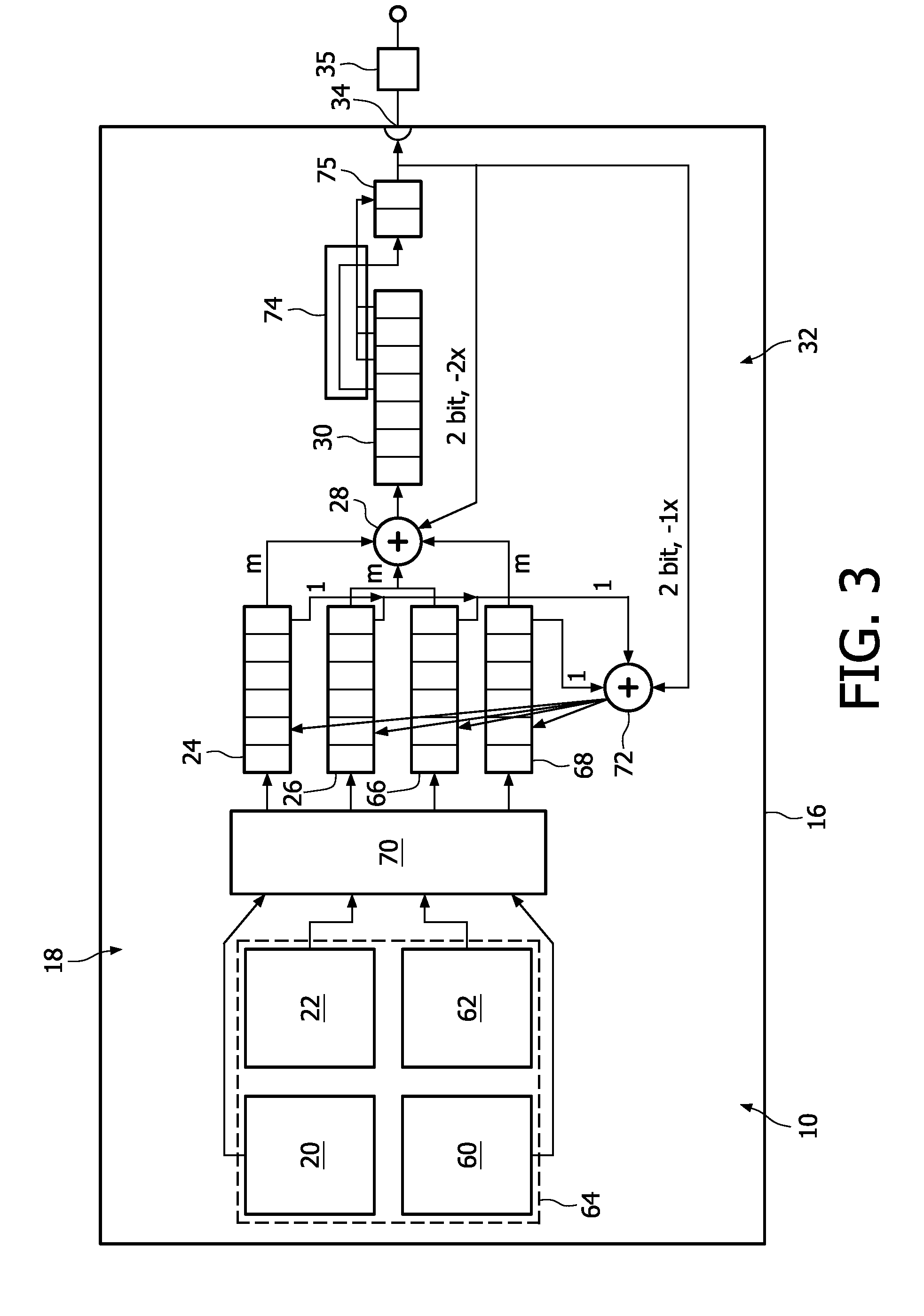
[0057]The structure and functionality of the apparatus 10 will now be described in more detail with reference to FIG. 3. First the structure of this second embodiment will be described, then the functionality of the apparatus 10 will be explained.
[0058]Apparatus 10 comprises first and second photon-sensitive elements 20, 22 and further third and fourth photon-sensitive elements 60, 62. These photon-sensitive elements 20, 22, 60, 62 are sub-pixels of a larger macro-pixel 64, which is indicated by the dashed line.
[0059]First, second, third and fourth photon-sensitive elements 20, 22, 60, 62 are respectively coupled to first, second, third and fourth integrators, 24, 26, 66, 68. Between the photon-sensitive elements 20, 22, 60, 62 and the integrators 24, 26, 66, 68 an A / D-converter 70 is arranged. The A / D-converter 70 individually processes the charge pulses from the photon-sensitive elements 20, 22, 60, 62 and outputs digital countable events to the respective integrators 24, 26, 66, ...
PUM
Abstract
The invention relates to an apparatus (10) for counting X-rayphotons (12, 14), in particular photons in a computer tomograph. The events from a first photon-sensitive element (20) are recorded in a first integrator (24), and the events coming from a second photon-sensitive element (22) are counted in a second integrator (26). A first summing unit (28) is provided for summing the values from the first and second integrators (24, 26) and a result signal to obtain a sum, wherein the result signal is obtained from a feedback device (30) being provided with the sum. It is there possible to reduce a total information density generated by the impinging photons (12, 14), so that a data stream with a reduced information density (or reduced data rate) is present at an output (34). The invention also relates to a corresponding imaging device (16) based on the detection of X-rayphotons (12, 14), in particular for medical use and to a method for counting X-rayphotons (12, 14), in particular photons in a computer tomograph.
Description
FIELD OF THE INVENTION[0001]The present invention relates to an apparatus, an imaging device and a method for counting X-ray photons, in particular photons in a computer tomograph.BACKGROUND OF THE INVENTION[0002]Computer tomography (CT, also called computed tomography) has evolved into a commonly used means, when it comes to generating a three-dimensional image of the internals of an object. The three-dimensional image is created based on a large number of two-dimensional X-ray images taken around a single axis of rotation. While CT is most commonly used for medical diagnosis of the human body, it has also been found applicable for non-destructive materials testing. Detailed information regarding the basics and the application of CT, can be found in the book “Computed Tomography” by Willi A. Kalender, ISBN 3-89578-216-5.[0003]One of the key innovative aspects in future CT and X-ray imaging is the energy-resolved counting of the photons which are let through or transmitted by the ob...
Claims
Application Information
Patent Timeline
Application Date:The date an application was filed.
Publication Date:The date a patent or application was officially published.
First Publication Date:The earliest publication date of a patent with the same application number.
Issue Date:Publication date of the patent grant document.
PCT Entry Date:The Entry date of PCT National Phase.
Estimated Expiry Date:The statutory expiry date of a patent right according to the Patent Law, and it is the longest term of protection that the patent right can achieve without the termination of the patent right due to other reasons(Term extension factor has been taken into account ).
Invalid Date:Actual expiry date is based on effective date or publication date of legal transaction data of invalid patent.

