Coater, method for manufacturing coated article, and fluid blowing

a coating and fluid blowing technology, applied in the direction of coatings, instruments, pretreated surfaces, etc., can solve problems such as unstable product quality, and achieve the effect of unstable product quality

Active Publication Date: 2010-05-06
TOSHIBA TEC KK
View PDF5 Cites 14 Cited by
  • Summary
  • Abstract
  • Description
  • Claims
  • Application Information

AI Technical Summary

Benefits of technology

[0006]The present invention has been made in order to solve the above-mentioned problem. An object of the present invention is to provide a coater, a method for manufacturing a coated article, and a fluid blowing unit, which are capable of uniform coating film formation within a surface.

Problems solved by technology

However, when the droplets are dried by drying such as air drying and reduced pressure drying, nonuniform distribution occurs in a solvent concentration of the atmosphere adjacent to the coated surface of a substrate due to an influence of air current or the like generated within the accommodating chamber.
This causes the quality of a product unstable.

Method used


Image

  • Coater, method for manufacturing coated article, and fluid blowing
  • Coater, method for manufacturing coated article, and fluid blowing
  • Coater, method for manufacturing coated article, and fluid blowing

Examples


first embodiment

[0035]A first embodiment according to the present invention will be described with reference to FIG. 1 to FIG. 7.

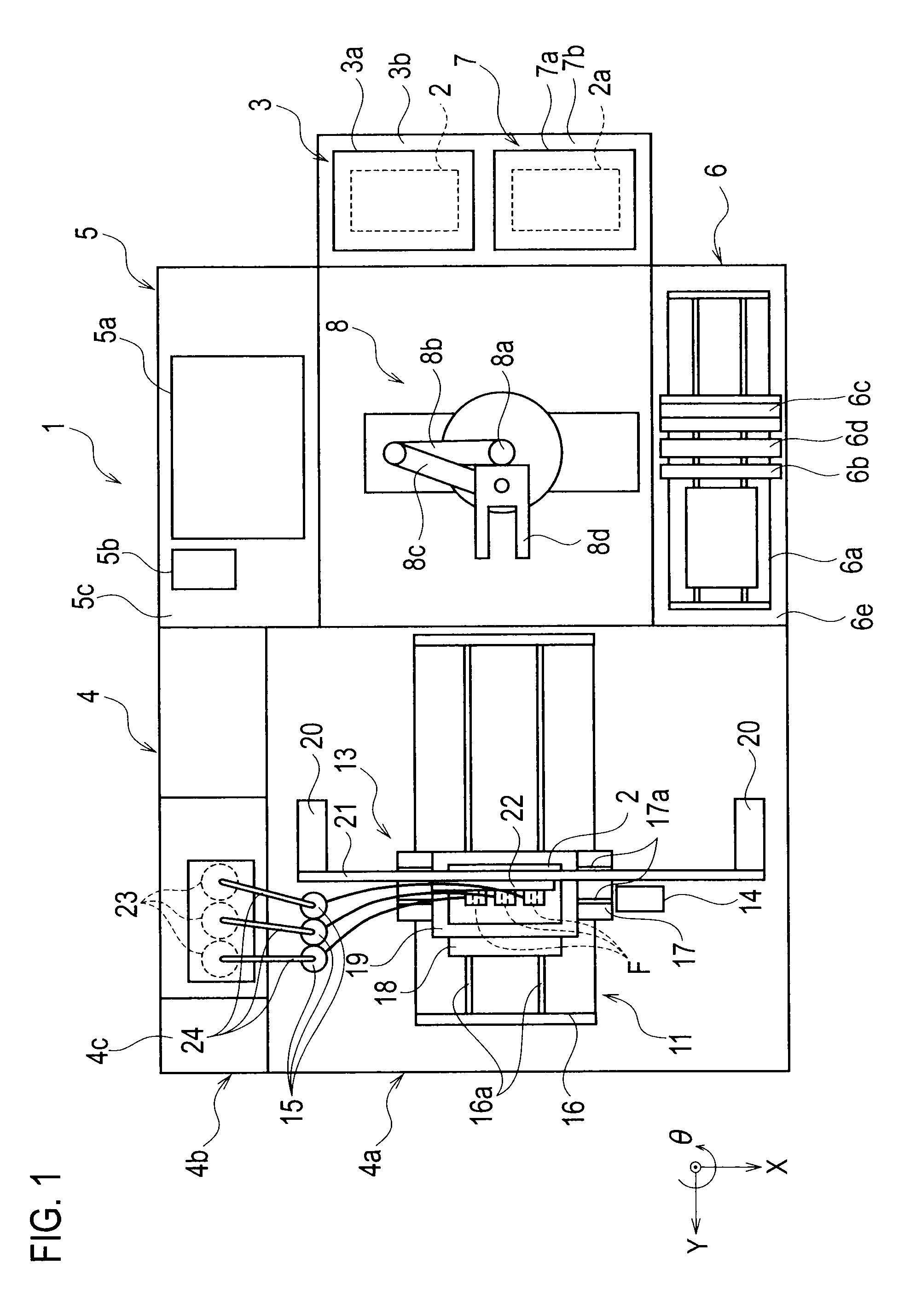
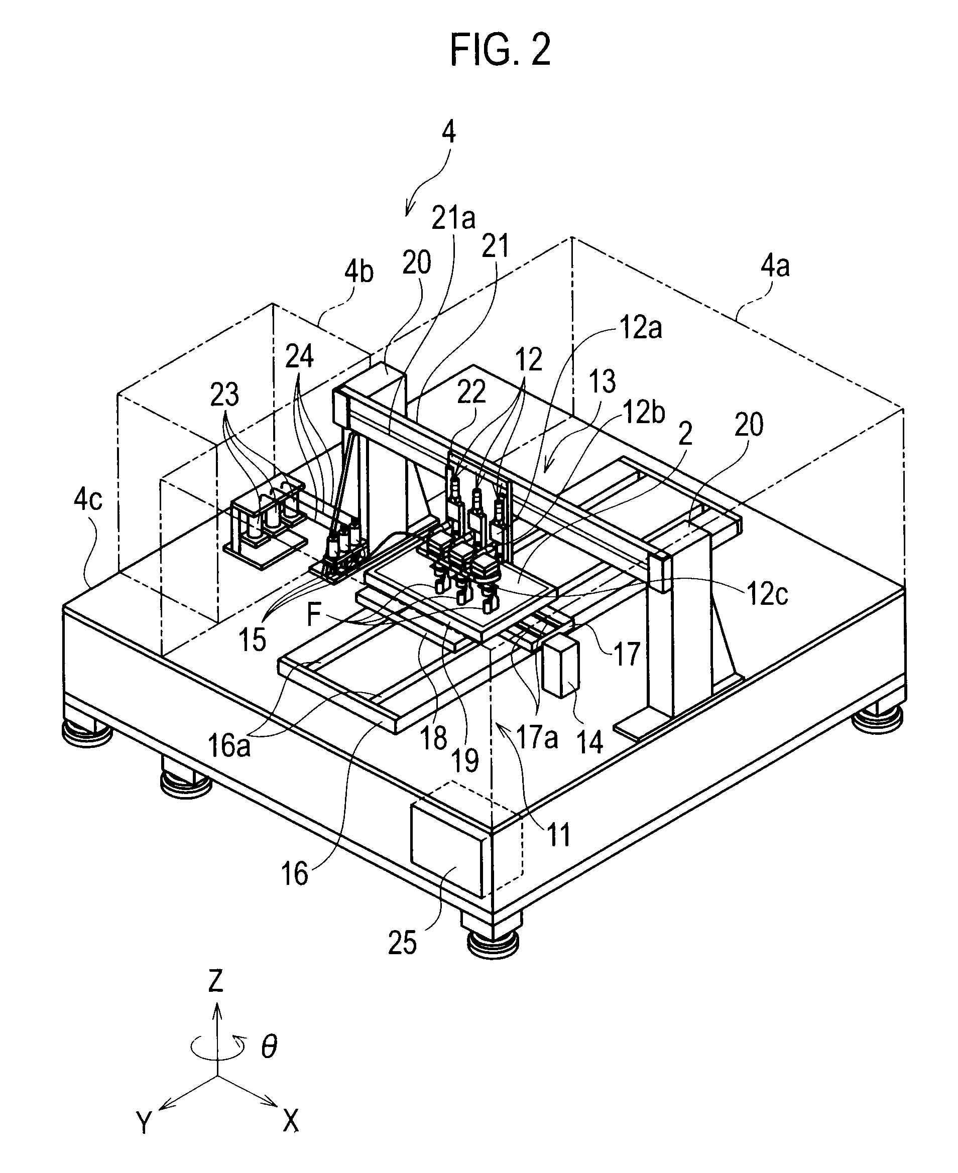
[0036]As shown in FIG. 1, a coater 1 according to the first embodiment of the present invention includes: a substrate accommodating part 3 which accommodates a substrate 2 which is an object to be coated; a droplet jet module 4 as a droplet jet part which ejects a solution (first solution) such as an ink in the form of a plurality of droplets to the substrate 2, and coats the substrate 2 with each droplet; a reduced pressure-drying module 5 as a reduced pressure-dryer which performs reduced pressure drying on the substrate 2 after the coating; a remoisturizing-drying module 6 as a remoisturizing-drying part which performs redissolution and re-drying on the substrate 2 subjected to the reduced pressure drying; a coated article-accommodating part 7 which accommodates a coated article 2a which is the substrate 2 subjected to the redissolution and re-drying; and a conveyor 8 ...

second embodiment

[0115]A second embodiment of the present invention will be described with reference to FIG. 8 to FIG. 11.

[0116]The second embodiment of the present invention is a modification of the first embodiment. Therefore, description will be given particularly on a part different from that in the first embodiment, i.e., a remoisturizing-drying module 6. Note that, in the second embodiment, description of the same parts as those described in the first embodiment will be omitted.

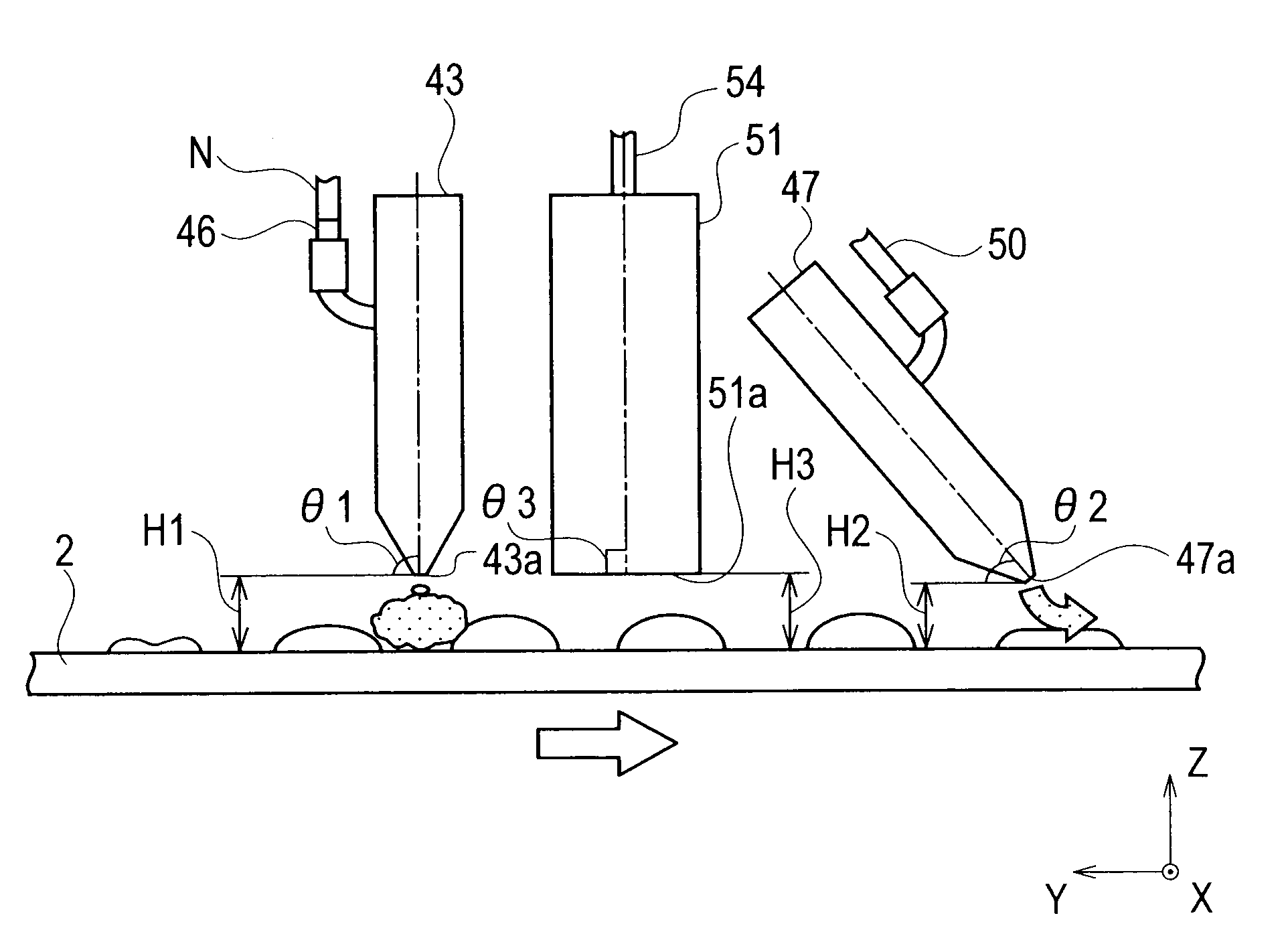
[0117]As shown in FIG. 8 and FIG. 9, the remoisturizing-drying module 6 includes the substrate moving mechanism 6a, the dissolution-blower 6b, the dry-blower 6c, and the exhaust part 6d, as well as a detector 6f which detects a spacing distance (first spacing distance) H4 to the surface (coated surface) of the substrate 2 moved by the substrate moving mechanism 6a.

[0118]The substrate moving mechanism 6a is formed by stacking a Y-axis-direction guide plate 41B and a substrate holding table 42. This substrate moving mech...

third embodiment

[0149]A third embodiment of the present invention will be described with reference to FIG. 12 and FIG. 13.

[0150]The third embodiment of the present invention is a modification of the first embodiment. Therefore, description will be given particularly on a part different from that in the first embodiment. Note that, in the third embodiment, description of the same parts as those described in the first embodiment will be omitted.

[0151]As shown in FIG. 12, a slit adjuster 81 is provided to the dissolution-blowing head 43. A blowing passage F1 is provided within this dissolution-blowing head 43. The blowing passage F1 is in communication with the blowing port 43a, which is an opening. In other words, the dissolution-blowing head 43 includes a head base 43A having: an inner surface Wa which forms the blowing passage F1 of a slit shape; and an outer surface Wb opposing to the inner surface Wa. Note that the blowing passage F1 is in communication with the dissolution gas-supplying pipe 46....


PUM


Abstract

A coater (1) includes: a droplet jet part (4) which ejects droplets of a first solution toward an object to be coated (2) to apply the droplets to the object to be coated (2); and a remoisturizing-drying part (6) which gives a residue of the first solution applied on the object to be coated (2) a solvent capable of dissolving the residue to form an applied body with a second solution containing the residue as a solute, and which dries the formed applied body with the second solution.

Description

TECHNICAL FIELD[0001]The present invention relates to a coater, a method for manufacturing a coated article, and a fluid blowing unit, and particularly relates to an apparatus that ejects droplets toward an object to be coated, a method for manufacturing a coated article to which a solute of the droplets adheres, and a unit that blows a fluid.BACKGROUND ART[0002]Coaters have been used not only in printing image information, but also in a film formation process when various flat panel displays are manufactured such as liquid crystal displays, organic EL (Electro Luminescence) displays, electron emitter displays, plasma displays, and electrophoretic displays.[0003]Such a coater includes: a droplet jet head (for example, ink jet head) which ejects a solution such as an ink in the form of droplets toward an object to be coated; a dryer which dries the droplets landed on the object to be coated; etc. This coater contributes to manufacturing of various products (coated articles) by landin...

Claims


Application Information

Patent Timeline
Patent Type & Authority Applications(United States)
IPC IPC(8): B05D3/04B05C9/12
CPCB05D3/105G02F1/1303H01L21/67028H01L21/6715H01L21/6776B05C5/00B05D1/26B05D3/00B05C9/00
Inventor SATO, TSUYOSHIKONDO, HIROYASUSAKURAI, NAOAKIYAMABE, JUNSEISOEDA, KATSUYUKIKOIZUMI, HIROSHIKIMURA, SHUICHIKINOSHITA, SHIZUO
Owner TOSHIBA TEC KK
Why Eureka
Try Eureka