Tuner device

a tuner device and tuner technology, applied in the direction of resonant circuits using central processing units, selective content distribution, television systems, etc., can solve the problems of local oscillation signal leakage from each minute frequency difference between the reference signals of the tuner devices, and difficulty in making the values of oscillation frequency of the reference signal sources equal to each other, so as to reduce the occurrence of noise and reduce the leakage of local oscillation signals.

Inactive Publication Date: 2010-05-06
SONY CORP
View PDF5 Cites 4 Cited by
  • Summary
  • Abstract
  • Description
  • Claims
  • Application Information

AI Technical Summary

Benefits of technology

[0011]Accordingly, the present invention has been achieved to provide a tuner device that can reduce the occurrence of the interference signal source when receiving broadcast waves of the same frequency.
[0013]The tuner device according to an embodiment of the present invention allows for reducing the leakage of a local oscillation signal, the leakage occurring in each of the tuner circuits, and an influence upon a different adjacent tuner circuit. Accordingly, the above-described tuner device can reduce the occurrence of an interference wave which becomes the source of a disturbance in the different adjacent tuner circuit even though the same frequency is selected. For example, the above-described tuner device can reduce the occurrence of a noise occurring in an image generated through a television receiver.

Problems solved by technology

Therefore, it becomes difficult to make the values of oscillation frequencies of the reference signal sources equal to each other.
Therefore, there is a minute frequency difference between the reference signals of the tuner devices.
If the above-described tuner devices are provided in proximity to each other, a local oscillation signal may leak from each of the tuner devices.
During the digital signal reception, the occurrence of a block noise, the blackout of an image, and so forth may occur due to the deterioration of appropriate carrier-to-noise (C / N) characteristics.

Method used


Image

  • Tuner device
  • Tuner device
  • Tuner device

Examples


Embodiment Construction

[0021]Hereinafter, best modes of performing the present invention (hereinafter referred to as embodiments of the present invention) will be described with reference to the attached drawings. The descriptions will be given in the following order.

1. Tuner device according to an embodiment of the present invention

2. Exemplary Modification

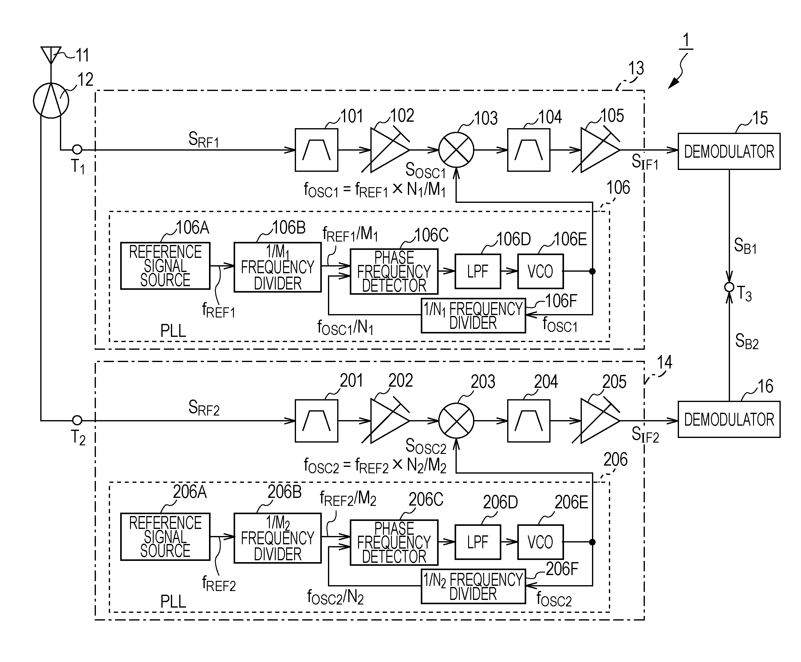
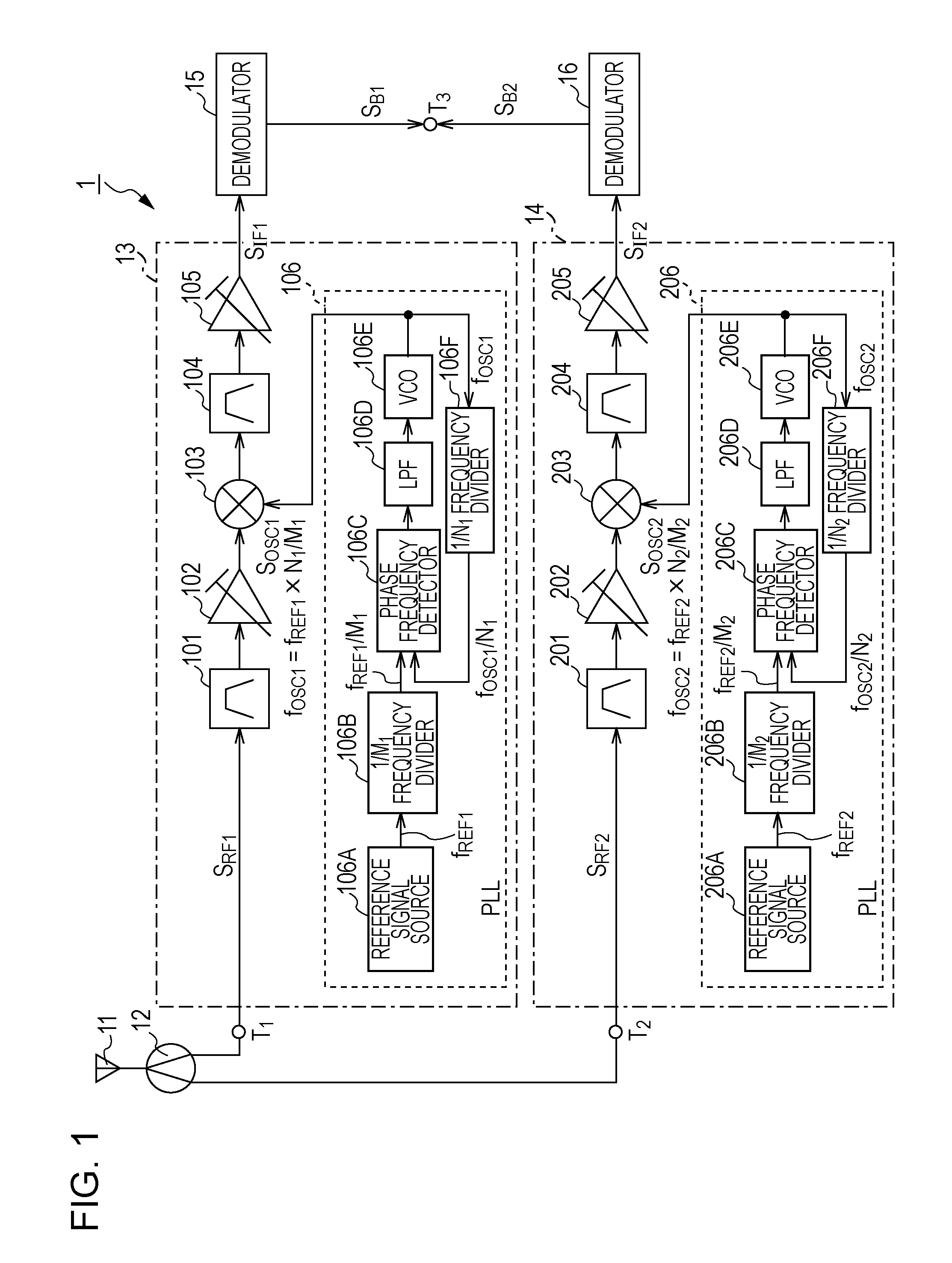
[0022]A tuner device according to an embodiment of the present invention includes a plurality of tuner circuits provided in the same cabinet, so as to receive a plurality of broadcast signals at the same time. FIG. 1 is a block diagram showing an exemplary internal configuration of a tuner device 1 according to an embodiment of the present invention.

[0023]A tuner device 1 shown in FIG. 1 includes an antenna 11, a distributor 12, input ends T1 and T2, tuner circuits 13 and 14, demodulators 15 and 16, and an output end T3 that are provided in the same cabinet. The tuner circuits 13 and 14 provided in the tuner device 1 can receive broadcast waves of the ...


PUM


Abstract

A tuner device includes tuner circuits, where each of the tuner circuits includes a radio frequency amplifier amplifying a radio frequency signal of a transmitted broadcast wave, a frequency mixing circuit performing frequency conversion for the transmitted radio frequency signal, and a local oscillation circuit transmitting a local oscillation signal to the frequency mixing circuit, wherein the local oscillation circuit includes, at least, a reference signal source, a first frequency divider, and a second frequency divider, oscillates a local oscillation signal having a local oscillation frequency, and makes a difference between local oscillation frequencies of the tuner circuits, the difference being generated when the tuner circuits receive the broadcast waves of the same frequency, greater than or equal to a predetermined value.

Description

BACKGROUND OF THE INVENTION[0001]1. Field of the Invention[0002]The present invention relates to a tuner device including a plurality of tuner circuits.[0003]2. Description of the Related Art[0004]A tuner device included in a television receiver selects the signal of a desired channel from among high frequency signals of television broadcasting, the high frequency signals including a very high frequency (VHF) signal, an ultra high frequency (UHF) signal, and so forth that are received through an antenna, performs frequency conversion for the selected signal so that the selected signal is converted into an intermediate frequency signal, and externally transmits the intermediate frequency signal.[0005]FIG. 5 shows an exemplary internal configuration of a tuner device 2 according to a related art. The tuner device 2 includes an antenna 21, an input end T11, a tuner circuit 22, a demodulator 23, an output end T12, and receives a terrestrial television broadcast wave.[0006]In the tuner d...

Claims


Application Information

Patent Timeline
Patent Type & Authority Applications(United States)
IPC IPC(8): H04B1/18H04B1/10H04N5/44
CPCH03J1/005H03J1/0083H04N5/455H04N21/4263H04N21/4382H04N5/50H03J5/00
Inventor IKEDA, MITSURU
Owner SONY CORP
Why Eureka
Try Eureka