Ultrasonic diagnostic device

a diagnostic device and ultrasonic technology, applied in the field of ultrasonic diagnostic devices, can solve the problems of inability to accurately estimate the risk of the development of arteriosclerosis, the degree of narrowing but also the ease of plaque tear, and the inability to accurately evaluate the degree of arteriosclerosis with the imt alone, etc., to accurately estimate not only the shape, accurate determine the risk of arteriosclerosis, and understand the movement state of a subject region.

Active Publication Date: 2010-05-06
FUJIFILM CORP
View PDF1 Cites 87 Cited by
  • Summary
  • Abstract
  • Description
  • Claims
  • Application Information

AI Technical Summary

Problems solved by technology

However, since the IMT is an index showing only the morphological change of a carotid artery, but not the dynamic characteristic of a blood vessel, it is not appropriate to evaluate the degree of arteriosclerosis with the IMT alone.
Thus, it is impossible to correctly estimate the risk for the development of arteriosclerosis either by the diagnosis of the IMT or the diagnosis of the elastic index showing the dynamic characteristic of a blood vessel, with the result that it is necessary to observe the both of them in a composite manner.
In recent years, it has become obvious that, in cerebral infarction, ischemic cardiac disease and the like, not only the degree of the narrowing but also the ease of the tear of plaque are problematic.
However, these elastic indices involve, for example, the following problems: (a) it is necessary to track the slight displacement of a moving blood vessel wall; (b) a probe is likely to be displaced from an observed location due to the hand shake of an operator and the body movement of a person to be tested; and (c) when it is impossible to obtain a clear image due to the person to be tested or the like, it is difficult to obtain highly reproducible data.
The main reason for the failure to obtain stable data is that variations in brightness information or phase information, noise in the form of a spike that is abruptly produced or the like cause erroneous tracking.
As described above, various inventions are disclosed that distinguish between the stable data and the error data so that an operator can obtain reliable data; however, in fact, required accuracy in an operation is disadvantageously high, and the operator is not satisfied with such determination.
Moreover, disadvantageously, from the obtained values on a stiffness parameter β, a strain and an elastic modulus, it is difficult for an examiner such as a doctor to visually image and understand the movement state.
In this method, the temporal change of a tissue on a line of interest can be easily recognized but there is a problem in which the method is not appropriate for observing the movement of the entire tissue.
Furthermore, in patent document 8, there is disclosed a three-dimensional ultrasonic imaging system; it can three-dimensionally display the position of a tissue but it cannot facilitate the three-dimensionally imaging and the understanding of the temporal change of a tissue.
In the examples shown in FIGS. 42A and 42B and FIGS. 43A and 43B, in the line A, data could be stably acquired not only in the i-frame but also in the j-frame; however, in the line B, since the image of a blood vessel wall was unstable due to variations in brightness information and phase, data could not be acquired stably, and tracking resulted in failure, with the result that it was impossible to measure elastic indices stably.
However, the diagnosis using the M mode image is not suitable for quantitatively measuring the minute displacement of movement of a blood vessel wall because, for example, the scale in image range is too different.
As described above, various inventions are disclosed that determine stable data and error data to allow an operator to acquire reliable data; however, in fact, the accuracy required for calculating elastic indices is too high, and thus the operator is not satisfied with the determination, with the result that the major problem is encountered in stably acquiring elastic indices.

Method used


Image

  • Ultrasonic diagnostic device
  • Ultrasonic diagnostic device
  • Ultrasonic diagnostic device

Examples


first embodiment

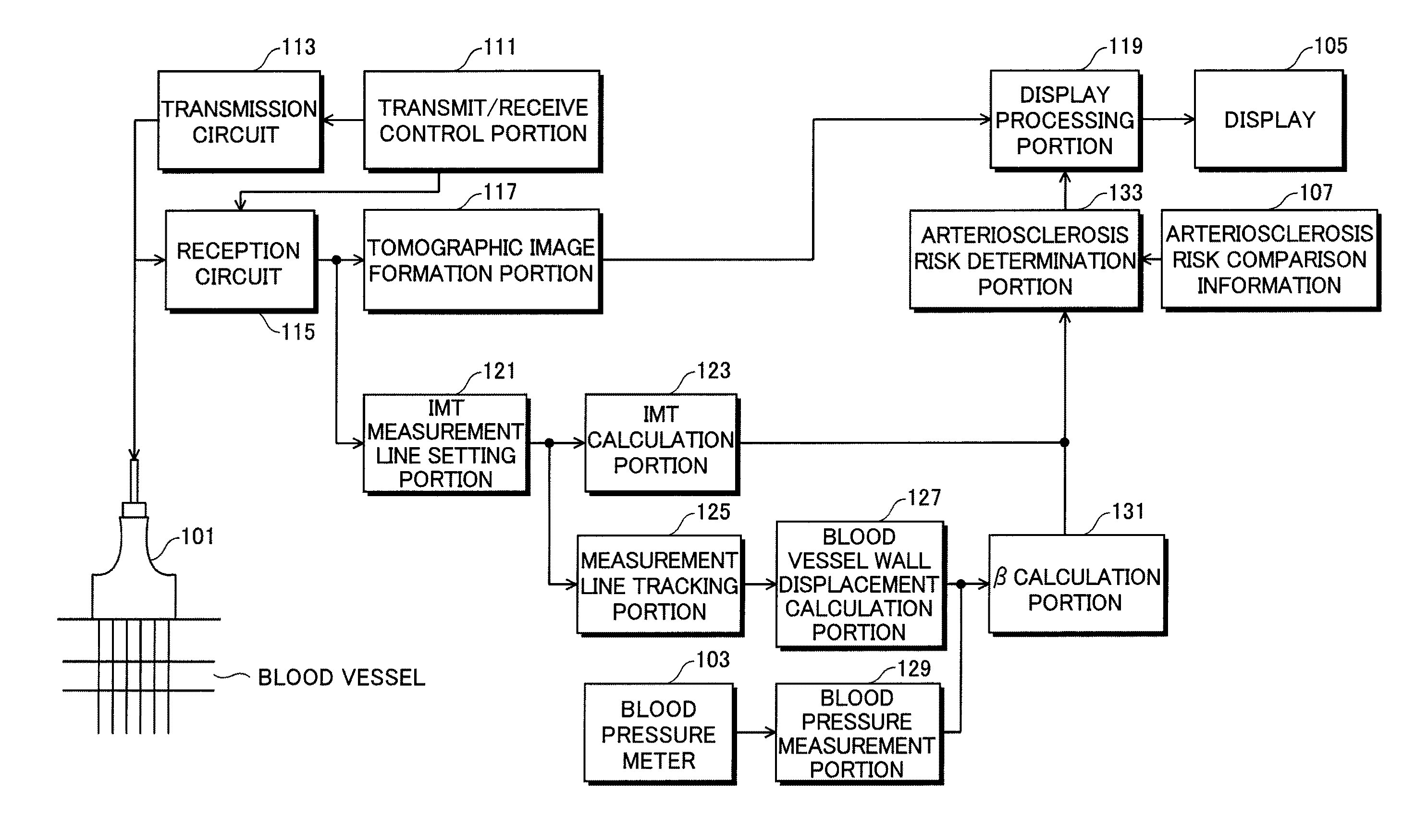
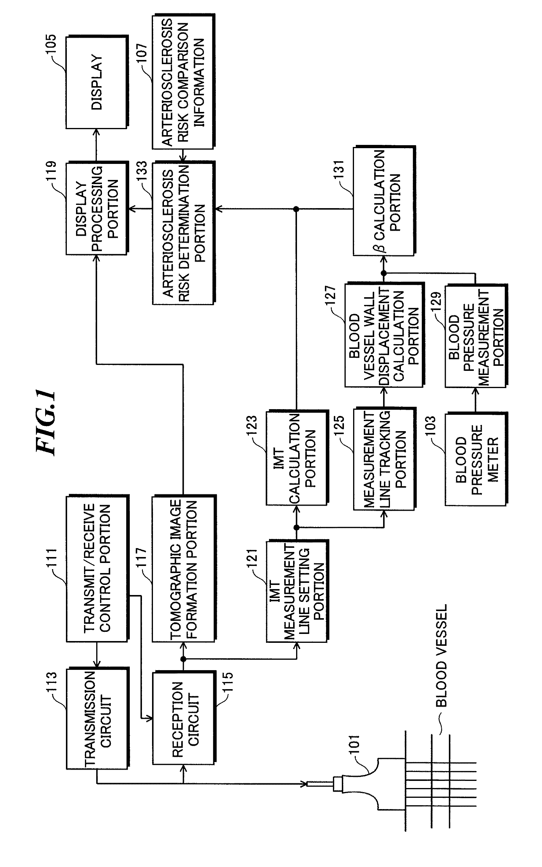
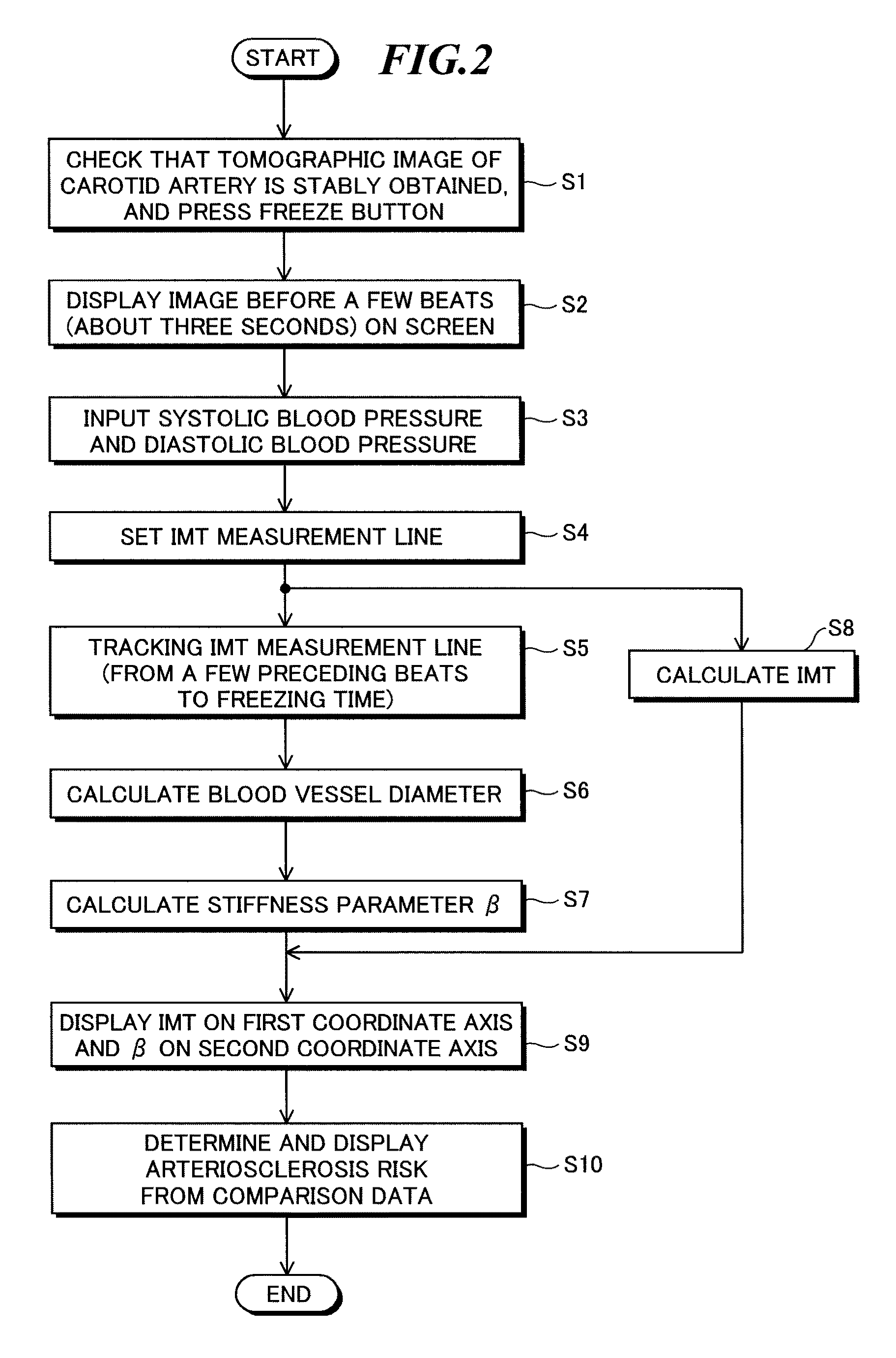
[0112]FIG. 1 is a block diagram showing the configuration of an ultrasonic diagnostic device according to a first embodiment of the present invention; FIG. 2 is a flowchart showing the procedure of a measuring method; FIGS. 3 and 4 are conceptual diagrams showing conditions in which the boundary lines of vascular membranes are set; FIG. 5 is a line diagram showing a state in which a blood vessel wall is changed; and FIGS. 6 and 7 show examples of a display screen.

[0113]The ultrasonic diagnostic device according to the first embodiment includes an ultrasonic probe for transmitting and receiving ultrasound and an ultrasonic diagnostic device main body. The ultrasonic diagnostic device main body has the functions of: controlling the transmitting and receiving of ultrasound; generating, based on an acquired reception signal, image data representing an ultrasonic image; measuring elastic indices indicating the intima media thickness (IMT) of a blood vessel and the dynamic characteristic ...

second embodiment

[0151]A second embodiment of the present invention will now be described. Although, in the first embodiment, the stiffness parameter β is used as the elastic index, the same holds true even if variations in blood vessel diameter, an elastic modulus and a WI (wave intensity) are used. In the second embodiment, an elastic modulus is used as the elastic index of a blood vessel.

[0152]FIG. 8 is a block diagram showing the configuration of an ultrasonic diagnostic device according to the second embodiment. Since FIG. 8 differs from FIG. 1 only in that the β calculation portion 131 is replaced with an elastic modulus calculation portion 132, like components are identified with the same reference numerals as the first embodiment, and their description will not be repeated.

[0153]In the case of the second embodiment using an elastic modulus as the elastic index of a blood vessel, the measurement line tracking portion 125 also tracks IMT measurement lines in the front wall and the boundary bet...

third embodiment

[0159]Like components are identified with like reference numerals, and their description will not be repeated.

[0160]FIG. 9 is a block diagram showing a configuration of an ultrasonic diagnostic device according to a third embodiment of the present invention, and the same parts as in FIG. 1 are identified with the same symbols, and their description will not be repeated.

[0161]As shown in FIG. 9, the ultrasonic diagnostic device according to this embodiment includes the ultrasonic diagnostic device main body 100 and the ultrasonic probe 101.

[0162]The ultrasonic transducer of the ultrasonic probe 101 transmits, based on a drive signal that is applied, ultrasound to the body under test such as a carotid artery blood vessel 300, receives ultrasonic echo reflected off the body under test and outputs an ultrasonic image signal along a measurement line set to the body under test.

[0163]The ultrasonic diagnostic device main body 100 includes: the transmit / receive control portion 111 that cont...


PUM


Abstract

In one aspect of the present invention, an object is to provide an ultrasonic diagnostic device that simultaneously displays an IMT and the elastic indices of a blood vessel to accurately determine, through composite observations, the risk for developing arteriosclerosis. According to one aspect of the present invention, there is provided an ultrasonic diagnostic device including: an ultrasonic probe that transmits ultrasound to a body under test and that receives ultrasonic echo reflected of the body under test to output a reception signal; image data generation means that generates, based on the reception signal output from the ultrasonic probe, image data representing an ultrasonic image on a blood vessel of the body under test; IMT measurement means that measures, based on the image data generated by the image data generation means, an IMT (intima media thickness) of the blood vessel; elastic index measurement means that determines, based on the image data generated by the image data generation means, a value representing an elastic index of the blood vessel; and display means that displays a two-dimensional coordinate system in which the IMT is represented on a first coordinate axis and the value representing the elastic index of the blood vessel is represented on a second coordinate axis.

Description

CROSS-REFERENCE TO RELATED APPLICATIONS[0001]The present application claims priority from Japanese Patent Application No. 2008-283280, filed Nov. 4, 2008, Japanese Patent Application No. 2008-299256, filed Nov. 25, 2008, Japanese Patent Application No. 2008-302049, filed Nov. 27, 2008 and Japanese Patent Application No. 2009-87787, filed Mar. 31, 2009, the contents of which are herein incorporated by reference in their entirety.BACKGROUND OF THE INVENTION[0002]1. Field of the Invention[0003]The present invention relates to an ultrasonic diagnostic device that has the function of simultaneously displaying the measurement results of the intima media thickness (IMT) and the elastic indices of a blood vessel to allow the risk of arteriosclerosis to be easily determined. The present invention also relates to an ultrasonic diagnostic device that visually displays variations in measurement results, and more particularly relates to an ultrasonic diagnostic device that displays, in an easily...

Claims


Application Information

Patent Timeline
Patent Type & Authority Applications(United States)
IPC IPC(8): A61B8/14
CPCA61B5/02007A61B5/022A61B5/7275A61B8/0858G16H40/63A61B8/486G16H50/30G16H30/40A61B8/485
Inventor MIYACHI, YUKIYA
Owner FUJIFILM CORP
Why Eureka
Try Eureka