Nasal cannula for acquiring breathing information

a technology of breathing information and cannula, which is applied in the field of cannula, can solve the problems of brain damage due to lack of oxygen or even death, increased fatigue, and other medical consequences, and achieve the effect of accurately and reliable performing air flow measurements and accurate and reliable identification

Inactive Publication Date: 2010-05-06
SALTER LABS
View PDF16 Cites 32 Cited by
  • Summary
  • Abstract
  • Description
  • Claims
  • Application Information

AI Technical Summary

Benefits of technology

[0011]It is, therefore, an object of the present invention to provide a nasal cannula structure suitable for accurately and reliably identifying the various forms of apnea and for accurately and reliable performing the air flow measurements necessary for polysomnogram diagnosis of the various forms of apnea.

Problems solved by technology

Sleep apnea and hypopnea have over time become to be recognized as significant and relatively common medical problems, the common consequence of which is that the CO2 level in a patient's blood increases while the oxygen level in the patient's blood decreases proportionately to the severity of the breathing irregularity, which may in turn lead to yet other medical consequences such as brain damage due to lack of oxygen or even death in extreme cases.
Other common consequences include disruptive sleep patterns, resulting in increased fatigue, lethargy, decreased ability to concentrate, increased irritability, headaches and other effects of a lack of adequate rest.
Mild, occasional sleep apnea, such as may be experienced during an upper respiratory infection is typically not significant, but chronic, severe obstructive sleep apnea can result in severe complications, including congestive heart failure.
This requirement, however, results in certain design problems in the cannulas to be used in polysomnograms.
It must also be noted that both mouth and nasal measurements for the detection of apnea are subject to yet further problems, and in particular by the response times, sensitivity and possible output signal amplitudes of various types of sensors.
For example, pressure sensors have faster response times but generate output signals that are of lower amplitude, so that it is difficult to measure lower levels of air flow.

Method used


Image

  • Nasal cannula for acquiring breathing information
  • Nasal cannula for acquiring breathing information
  • Nasal cannula for acquiring breathing information

Examples


Embodiment Construction

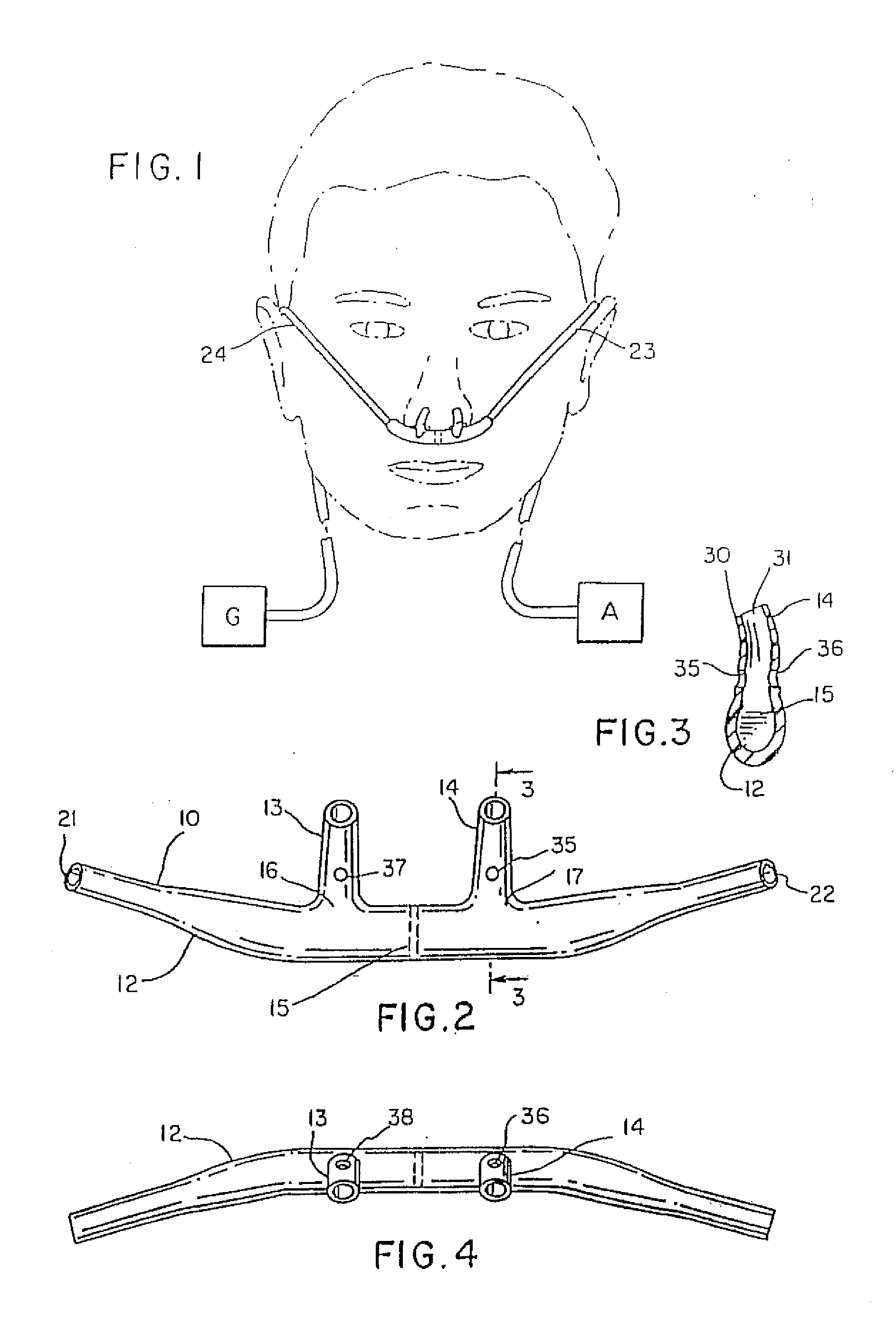
[0017]FIG. 1 is a frontal view of a normally positioned nasal cannula on a patient (shown in phantom) connected to a gas source (G) and a gas analyzer (A);

[0018]FIG. 2 is a rear view of the cannulas face piece shown in FIG. 1;

[0019]FIG. 3 is a partial cross section of a nare of the nasal cannula taken along the lines and arrows 3-3 of FIG. 2;

[0020]FIG. 4 is a top plan view of the nasal cannula of FIG. 2;

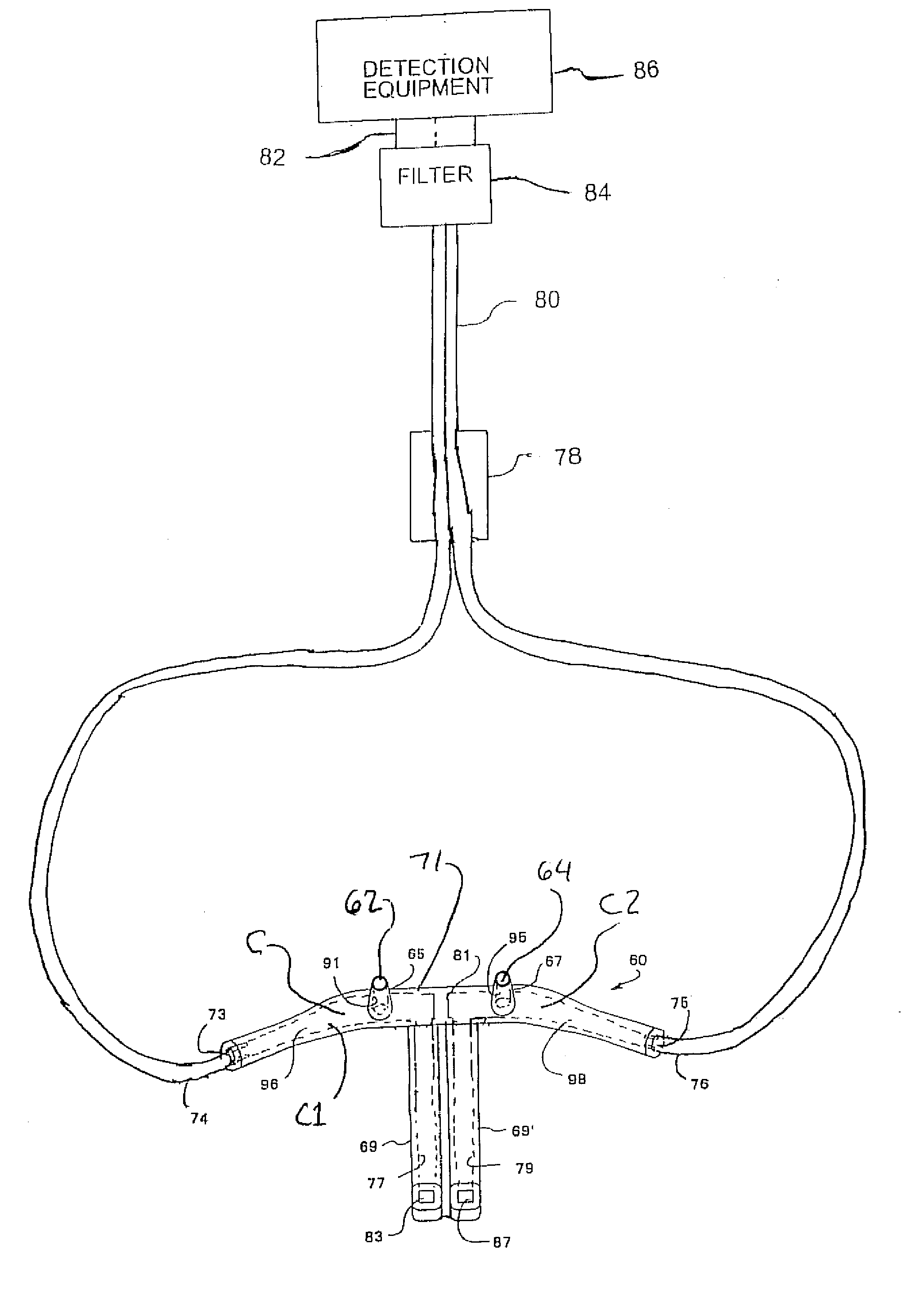
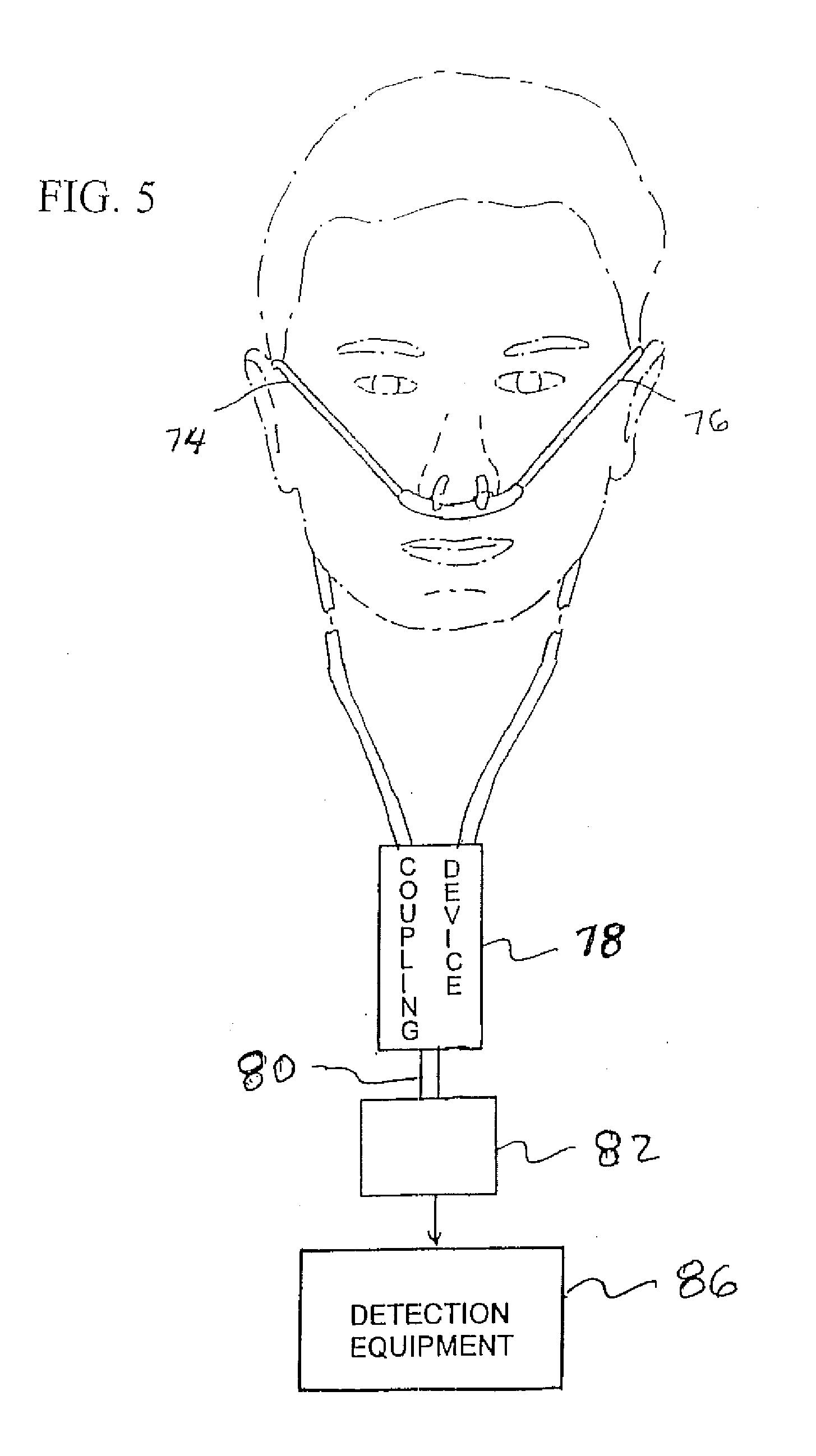
[0021]FIG. 5 is a diagrammatic view of a nasal cannula for connection to detection equipment to facilitate monitoring of breathing characteristics of a patient;

[0022]FIG. 6 is a diagrammatic view of a nasal cannula, with a mouthpiece, for connection to detection equipment to facilitate monitoring of breathing characteristics of a patient;

[0023]FIG. 7 is a diagrammatic view of a nasal cannula, with a mouthpiece but without any secondary openings in the nares, for connection to detection equipment to facilitate monitoring of breathing characteristics of a patient;

[0024]FIG. 8 is a diag...


PUM


Abstract

A nasal cannula for monitoring symptoms of sleep apnea and hypopnea, including an elongated main body having a main body chamber and first and second nares to be received within first and second nasal passages of a patient's nose and at least one mouthpiece extending to a patient's mouth. The main body chamber communicates with first and second cannula inlet/outlets and each nare and the mouthpiece includes a gas flow passage extending from the nostril or mouth to the main body chamber. At least one nasal gas flow sensor is located in an gas flow passage of at least one of the nares and at least one oral gas flow sensor located in the mouthpiece gas flow passage, preferably in the regions of the gas flow passages adjacent the main body chamber.

Description

[0001]This application is a continuation-in-part of provisional patent application Ser. No. 60 / 902,935 filed Feb. 22, 2007, which is a continuation-in-part of patent application Ser. No. 11 / 155,901 filed Jun. 17, 2005, which is a continuation-in-part of patent application Ser. No. 10 / 627,502 filed Jul. 25, 2003 which is a divisional of patent application Ser. No. 09 / 837,720 filed Apr. 18, 2001 which is a continuation of patent application Ser. No. 09 / 184,111 filed Nov. 2, 1998 which is a continuation of International Application PCT / US98 / 05573 filed Apr. 3, 1998 which claims the benefit of provisional patent application Ser. No. 60 / 045,080 filed Apr. 29, 1997.FIELD OF THE INVENTION[0002]The present invention relates to a cannula having a pair of nares and at least one mouthpiece, each nare and each mouthpiece having a primary aperture or opening formed in an end surface or wall thereof and defining a flow path into and out of the nare or mouthpiece for supplying a desired gas to a n...

Claims


Application Information

Patent Timeline
Patent Type & Authority Applications(United States)
IPC IPC(8): A61B5/087
CPCA61M16/0666A61M2016/0021A61M2016/0027A61M16/085A61M2202/0208A61M2210/0625A61M2230/432A61M2016/0039A61M16/1055A61M2205/7536A61M16/106
Inventor CURTI, JAMES N.CHUA, JAMESSALTER, PETER W.
Owner SALTER LABS
Why Eureka
Try Eureka