
Driving assistance method for motor vehicle

a technology for motor vehicles and assistance methods, applied in brake systems, instruments, braking systems, etc., can solve problems such as inability to function, driver failure to realize, and obstacle will be struck at full speed, so as to reduce noise and vibration of motor vehicles, reduce the risk of collision, and improve the braking reaction time

Inactive Publication Date: 2010-05-06
VALEO VISION SA
View PDF13 Cites 26 Cited by
  • Summary
  • Abstract
  • Description
  • Claims
  • Application Information

AI Technical Summary

Benefits of technology

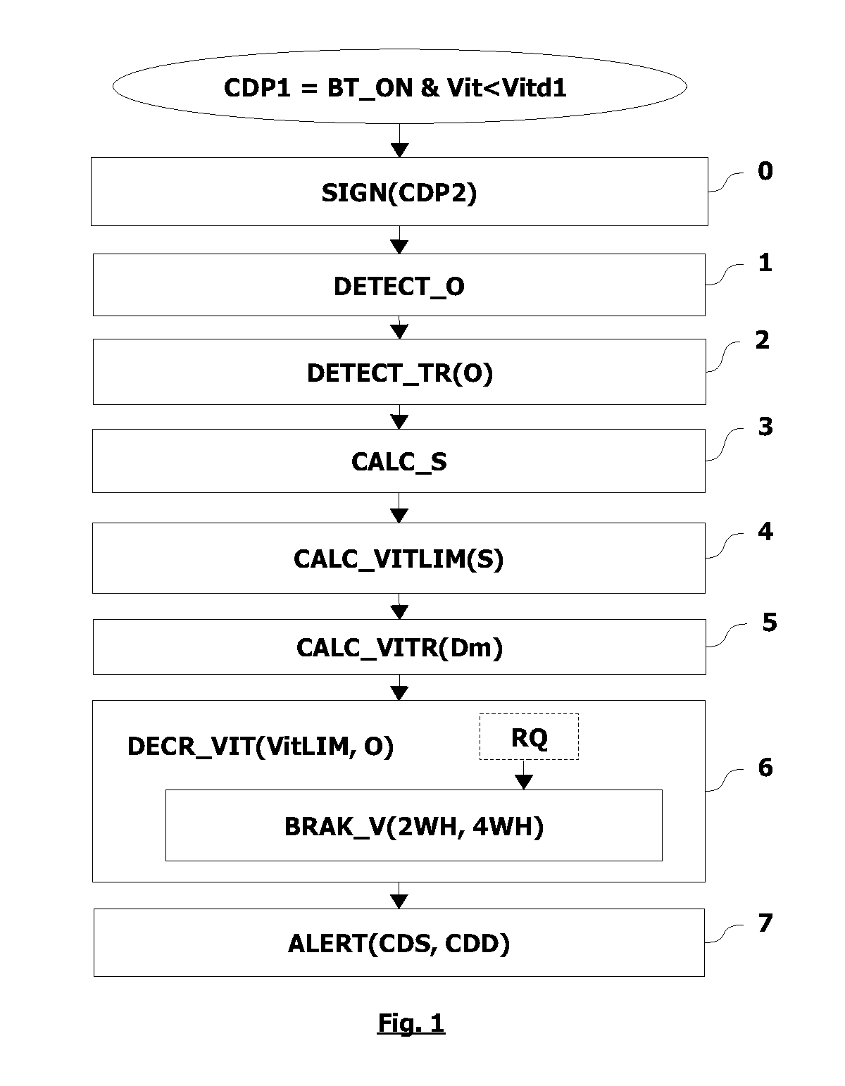
[0013]if an obstacle is detected, automatically reducing the speed of the motor vehicle if this is greater than the speed limit.
[0038]if an obstacle is detected, automatically reducing the speed of the motor vehicle if this is greater than the speed limit.

Problems solved by technology

One disadvantage of this state of the art is that it only operates in parking situations, since above these very low speeds, the assistance method for parking maneuver is not triggered and thus does not function.
The risk is that if the speed of the vehicle is above the triggering speed of the assistance method, the driver fails to realize this and nevertheless relies on the driving assistance system.
However, as the assistance system is not activated, it will not assist the driver, and the obstacle will be struck at full speed.

Method used


Image

  • Driving assistance method for motor vehicle
  • Driving assistance method for motor vehicle
  • Driving assistance method for motor vehicle

Examples


first embodiment

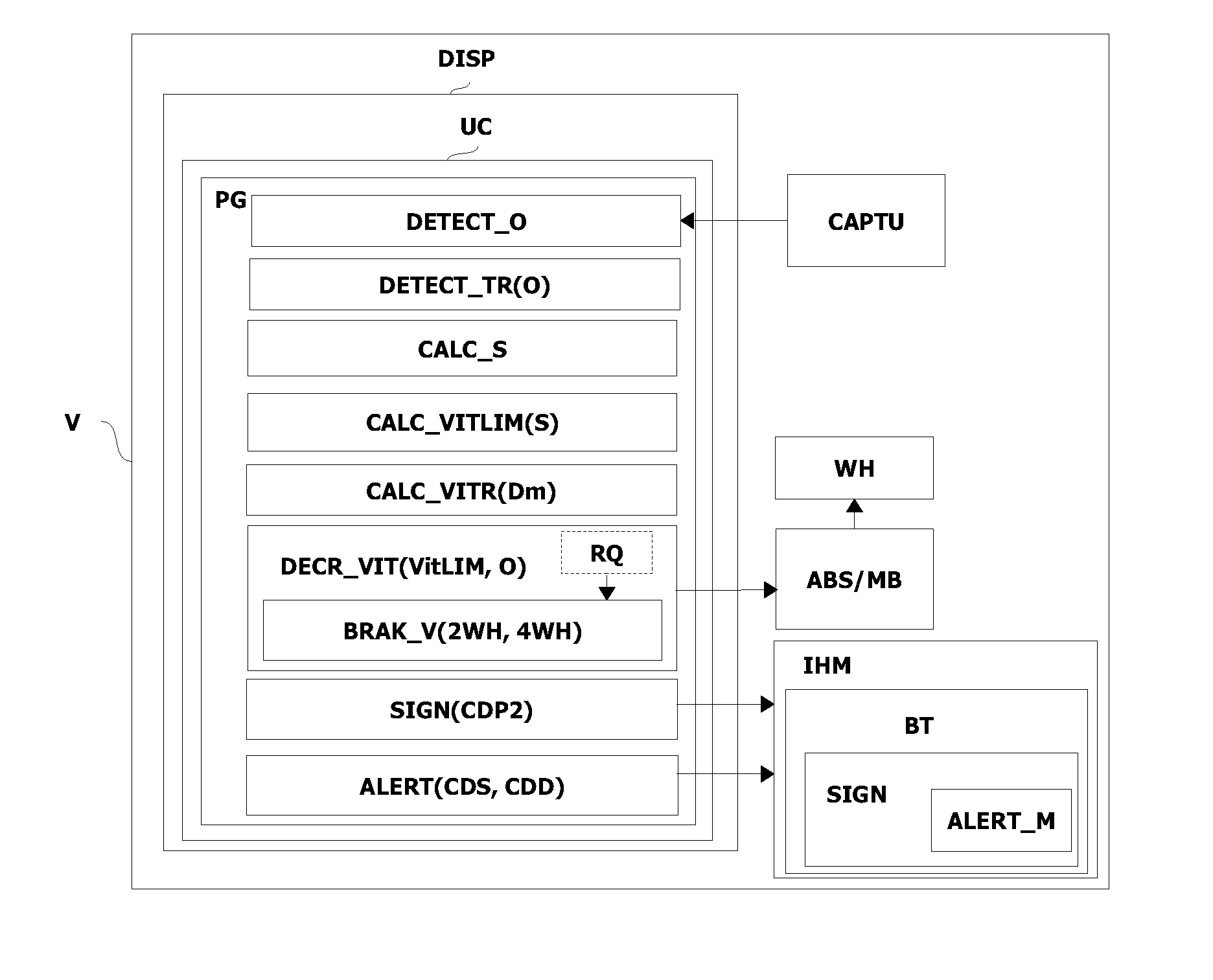
[0175]In a first embodiment, the alert function ALERT generates a first level of alert when safe conditions CDS are attained.

[0176]In one non-limitative variant, the safe conditions CDS are:[0177]a vehicle speed Vit which lies within a first interval of speeds allowing the motor vehicle V to be stopped without striking an obstacle O which has been detected. In one non-limitative example, the interval lies between 3 and 7 km / h; and[0178]the observation of internal control parameters PIC forecasting a potential danger of colliding with the obstacle O; thus, the alert function ALERT warns the driver so that he can increase the braking request by foot via the brake pedal in addition to the automatic reduction of the vehicle speed Vit.

[0179]In one non-limitative example, the internal control parameters PIC are:[0180]a predicted distance Dp from the obstacle O evaluated depending on the acceleration / deceleration of the motor vehicle V. In one non-limitative example, Dp=Vit2 / (2×deceleratio...

second embodiment

[0186]In a second embodiment, the alert function ALERT generates a second level of alert when dangerous conditions CDD are reached.

[0187]In one non-limitative variant, the dangerous conditions CDD are:[0188]a vehicle speed Vit which lies in a second interval of speeds which do not allow the motor vehicle V to stop without colliding with an obstacle O detected. In one non-limitative example, the interval lies between 7 and 20 km / h; and[0189]the observation of the internal control parameters, described above, forecasting a danger of colliding with the obstacle O.

[0190]In this case, the driving assistance causes the speed of the motor vehicle V to diminish, but the obstacle O will be struck before the motor vehicle V has stopped.

[0191]Obviously, these two embodiments are used in combination.

[0192]Thus, the method described enables the damage caused to an obstacle to be reduced if there is a collision, by reducing the speed of the motor vehicle before the collision takes place, and when...


PUM


Abstract

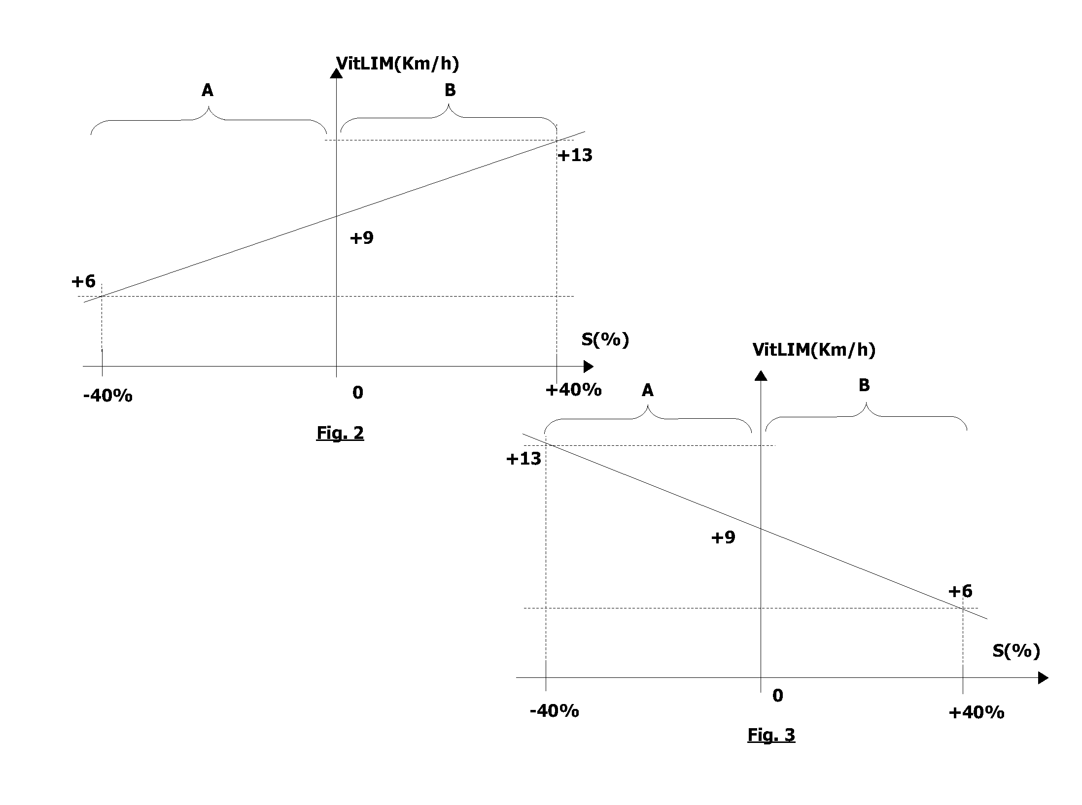
A driving assistance method for a motor vehicle is disclosed. It is characterised in that the method comprises the steps of detecting an obstacle located in proximity to the motor vehicle, calculating the slope of a road on which the motor vehicle is capable of travelling, determining, depending on the calculated slope of the road, a speed limit beyond which the motor vehicle will strike the obstacle, and if an obstacle is detected, automatically reducing the speed of the motor vehicle if this is greater than the speed limit.

Description

CROSS-REFERENCE TO RELATED APPLICATION[0001]This application claims priority to French Application No. 0806122 filed Nov. 3, 2008, which application is incorporated herein by reference and made a part hereof.BACKGROUND OF THE INVENTION[0002]I. Field of the Invention[0003]The present invention concerns a driving assistance method for a motor vehicle, and an assistance device allowing the method to be implemented.[0004]It is especially suitable for use in the domain of motor vehicles.[0005]II. Description of the Related Art[0006]In the domain of motor vehicles, there is a driving assistance method for a motor vehicle known in the prior art, which is used when a driver of the motor vehicle wants to park. It is therefore triggered at very low speeds, generally from 2 to 3 km / h. It allows the driver to avoid colliding with an obstacle during a parking maneuver. A method of this type is commonly known in English as “Park Assist”. One disadvantage of this state of the art is that it only o...

Claims


Application Information

Patent Timeline
IPC IPC(8): G06F7/00B60T7/12G01S15/00B60W30/08B60W40/10
CPCB60T7/22B60T2201/024B60T2201/10B60W30/06B60W30/095B60W40/105B60W2550/142B60W2552/15
Inventor GROULT, XAVIER
Owner VALEO VISION SA
Learn More