

Method and system for abnormality diagnosis of very low speed rotating machine
- Summary
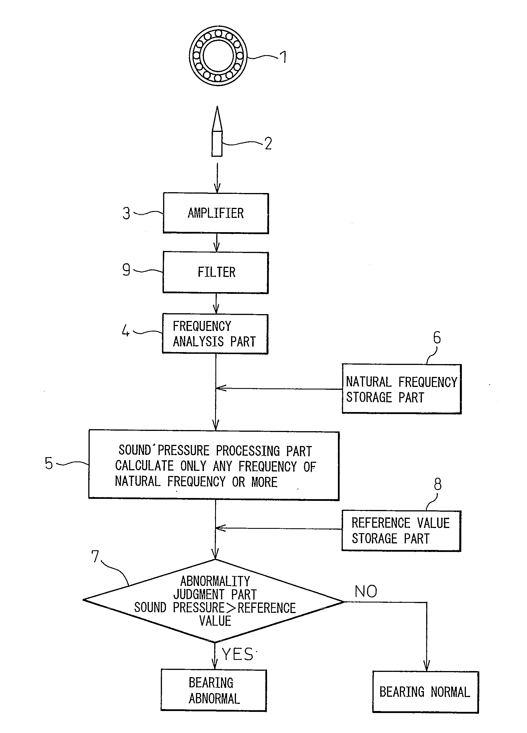
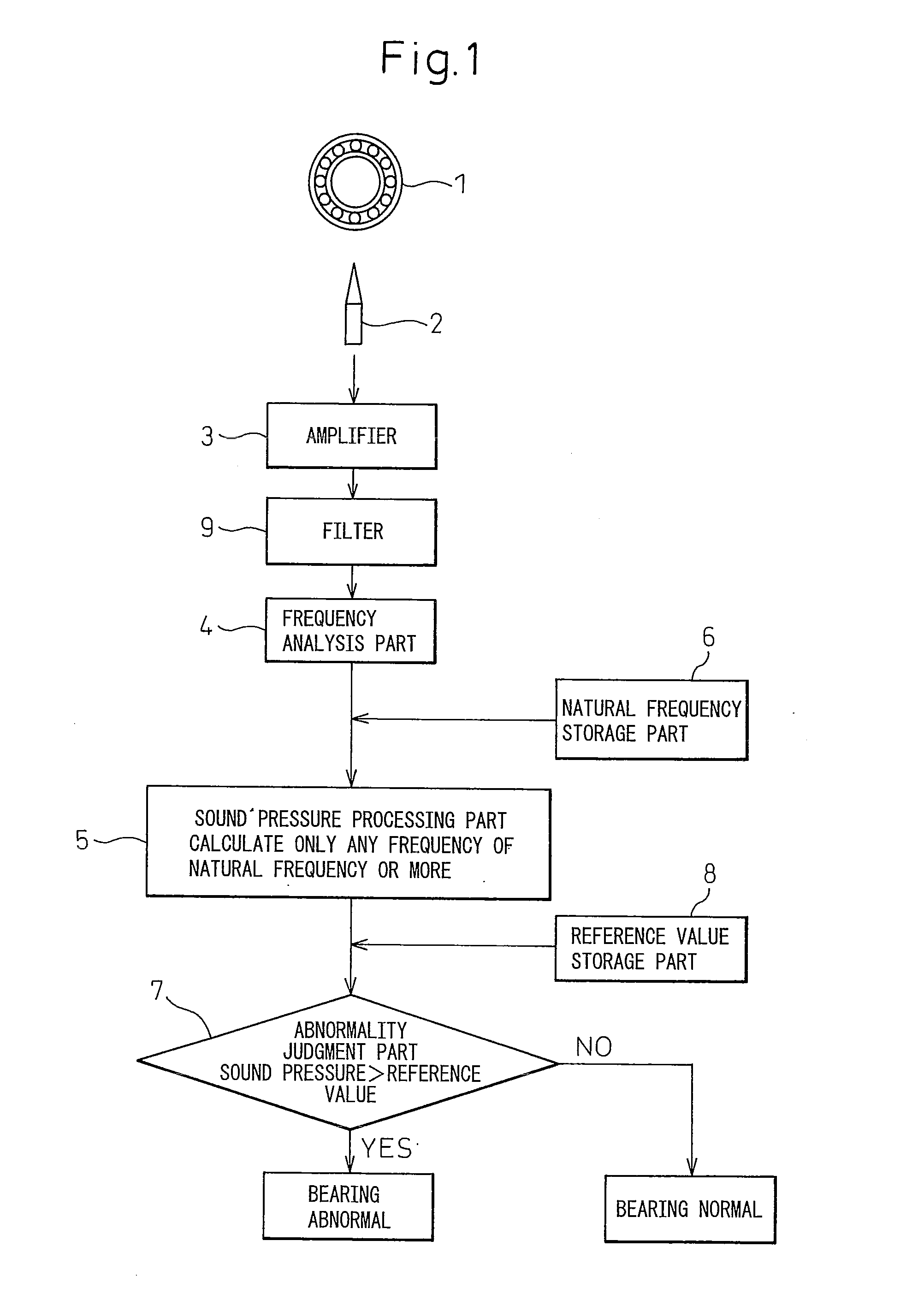
- Abstract
- Description
- Claims
- Application Information
AI Technical Summary
Benefits of technology
Problems solved by technology
Method used
Image

Examples
example 1
[0050]FIG. 3 and FIG. 4 show the results of analysis of self-aligned roller bearings of continuous casting machines rotating at 0.5 rpm. These were obtained by bringing a microphone into contact with the bearings and are examples where the bearing holders are damaged and rollers clash and the load increases.
[0051]FIG. 3(a) shows the sound spectrum of a bearing of a normal #1 roll. The sound pressure of the low frequency region including the natural frequency (in this example, 350 Hz) is dominant. No special characteristics can be found at 500 Hz or more. FIG. 3(b) shows the sound spectrum of a bearing of a damaged #8 roll. The low frequency region of 500 Hz or less is the same as the bearing of the normal #1 roll, but several peaks are seen near 1 to 2 kHz.
[0052]FIG. 4 shows the spectral effective value of a frequency of a frequency band of 500 Hz or more for each bearing excluding the frequency band near the natural frequency. With an average sound pressure, as will be understood f...
example 2
[0056]FIG. 6 shows the analysis results obtained by bringing a microphone into contact with the bearing when the outer race cracks in a self-aligned roller bearing of a continuous casting machine rotating at 3 rpm.
[0057]FIG. 6(a) shows the sound spectrum of a normal bearing. This example is also an example where screening by listening to the sound would lead to diagnosis of no abnormality probably being present. A sound pressure of 1 kHz or less due to the natural frequency or contact resonance was dominant. No peaks were seen at 1 kHz or more.
[0058]FIG. 6(b) shows the sound spectrum of a damaged bearing. Near 3 kHz, a sharp peak is seen. It could be judged that a crack had occurred resulting in contact of the rollers and broken face of the outer race of the bearing and the accompanying sound was remarkable.
[0059]In this example, unlike Example 1, it was not possible to clearly judge an abnormality by screening by sound without a filter, but it was also not possible to diagnose ther...
example 3
[0060]FIG. 7 also shows the sound spectrum obtained by setting a microphone close to the bearings without contact in a facility the same as Example 2. This facility has cooling water or air ejection parts near where the microphone is set and therefore has large noise, but a peak could be confirmed near 3 kHz. By suitably setting the reference value of the spectral average value or effective value, it is possible to detect abnormalities.
[0061]In this example, abnormalities could not be judged with screening by sound using a filter due to the effects of noise, but according to the present invention, it became possible to judge abnormalities.
PUM
 Abstract
Description
Claims
Application Information