

Rotational coupling device with wear compensation structure
a technology of rotating coupling and structure, which is applied in the direction of magnetically actuated clutches, mechanical actuators, mechanical apparatus, etc., can solve the problems of reducing the useful life of the device, wear on the engagement surfaces of the armature, the rotor and the brake plate, and increasing the air gap between the armature. , to achieve the effect of prolonging the service life of the devi
- Summary
- Abstract
- Description
- Claims
- Application Information
AI Technical Summary
Benefits of technology
Problems solved by technology
Method used
Image

Examples
Embodiment Construction
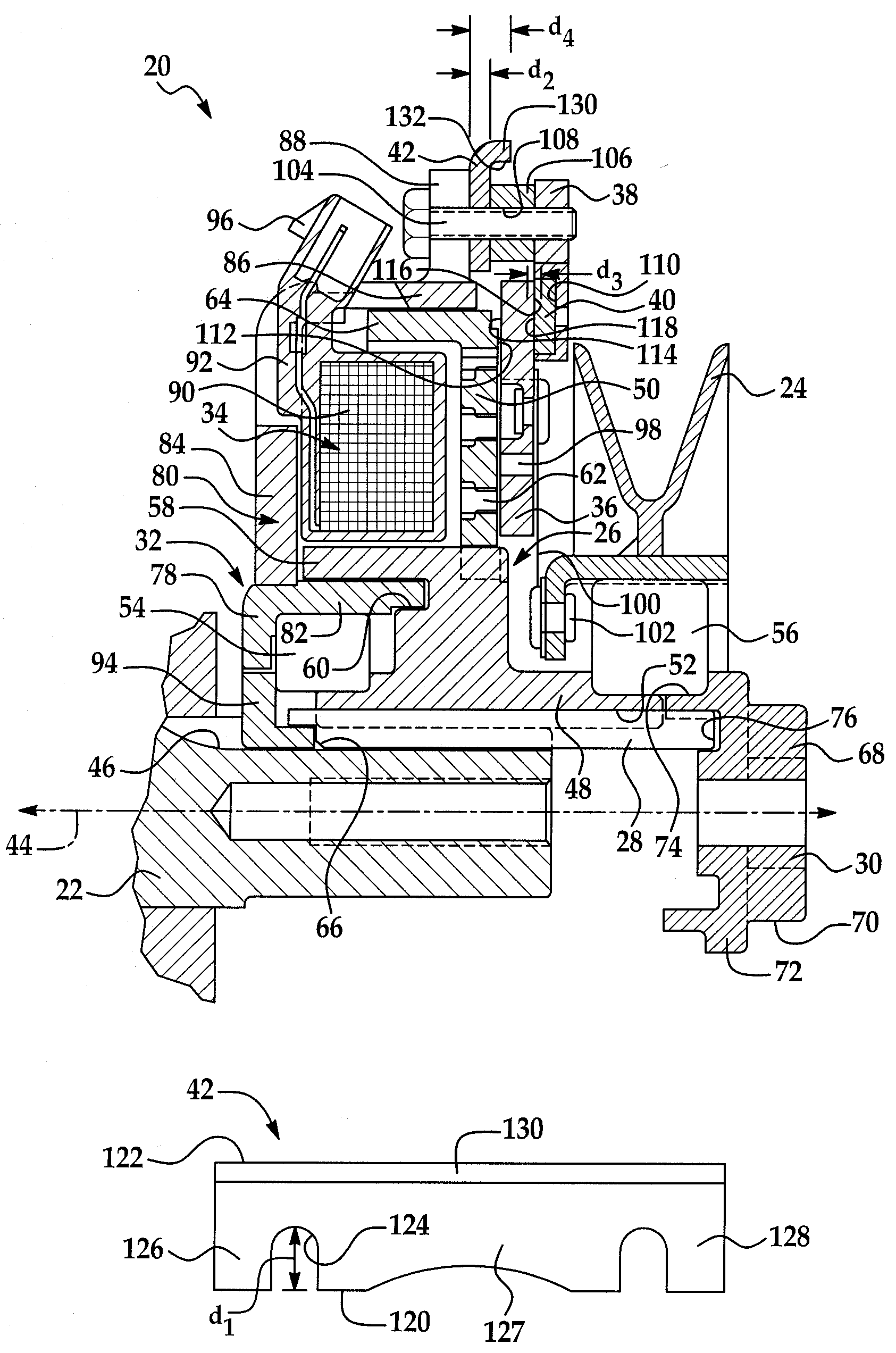
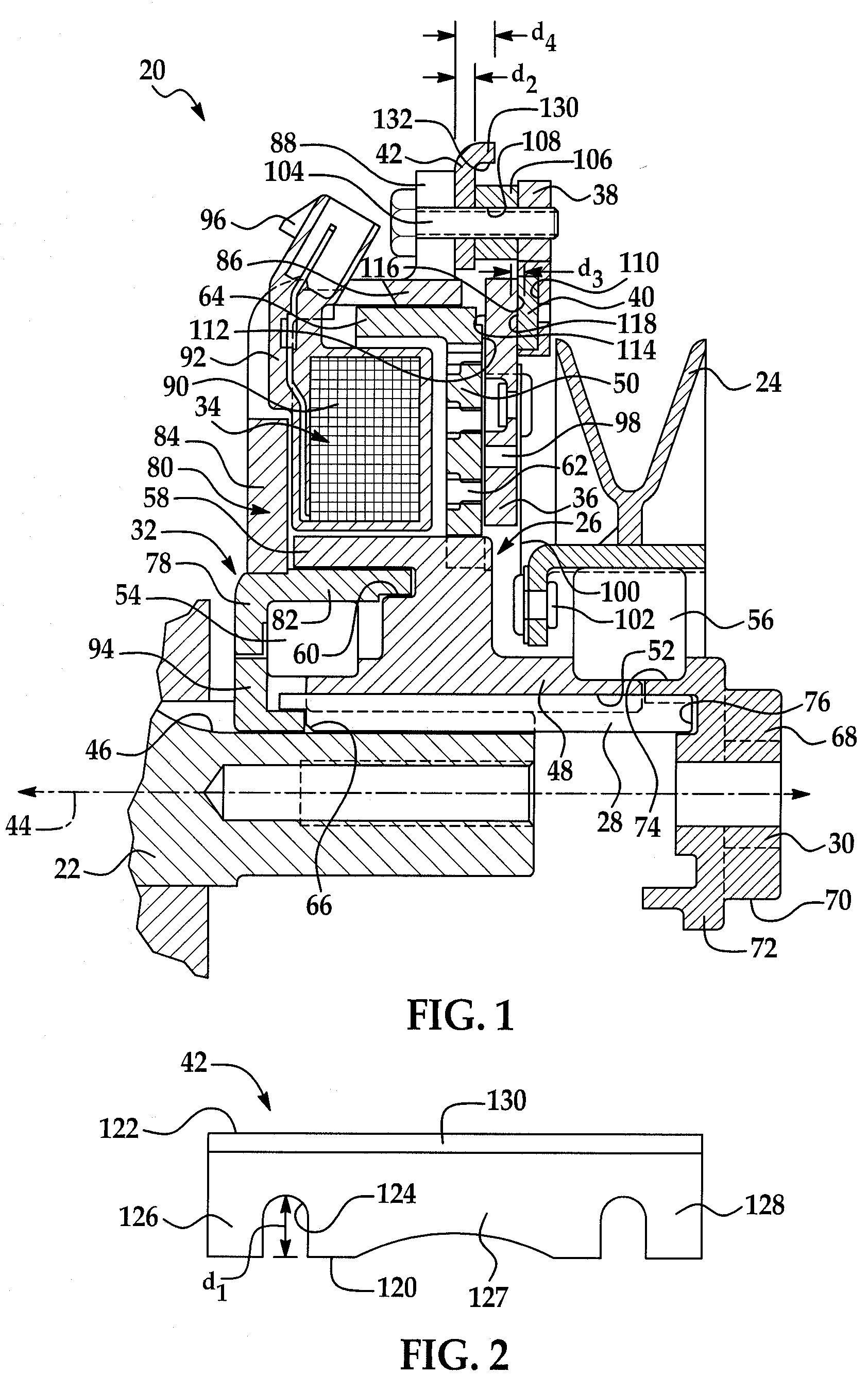
[0020]Referring now to the drawings wherein like reference numerals are used to identify identical components in the various views, FIG. 1 illustrates a rotational coupling device 20 in accordance with one embodiment of the present invention. Device 20 functions as a clutch to selectively transfer torque from an input shaft 22 to an output member 24. Device 20 also functions as a brake on output member 24 when torque is not being transferred to output member 24. Device 20 may be provided for use in a riding lawnmower or similar device. It will be understood by those of ordinary skill in the art, however, that device 20 may be used in a wide variety of applications requiring a clutch or brake. Device 20 may include a rotor 26, a key 28, a spacer 30, a field shell 32, an electrical conduction assembly 34, an armature 36, a brake plate 38, one or more permanent magnets 40 and a removable shim 42.
[0021]Input shaft 22 provides a source of torque for driving output member 24. Shaft 22 may...
PUM
 Abstract
Description
Claims
Application Information