
Imaging reader with efficient laser illumination

Inactive Publication Date: 2010-05-13
SYMBOL TECH INC
View PDF3 Cites 1 Cited by
  • Summary
  • Abstract
  • Description
  • Claims
  • Application Information

AI Technical Summary

Benefits of technology

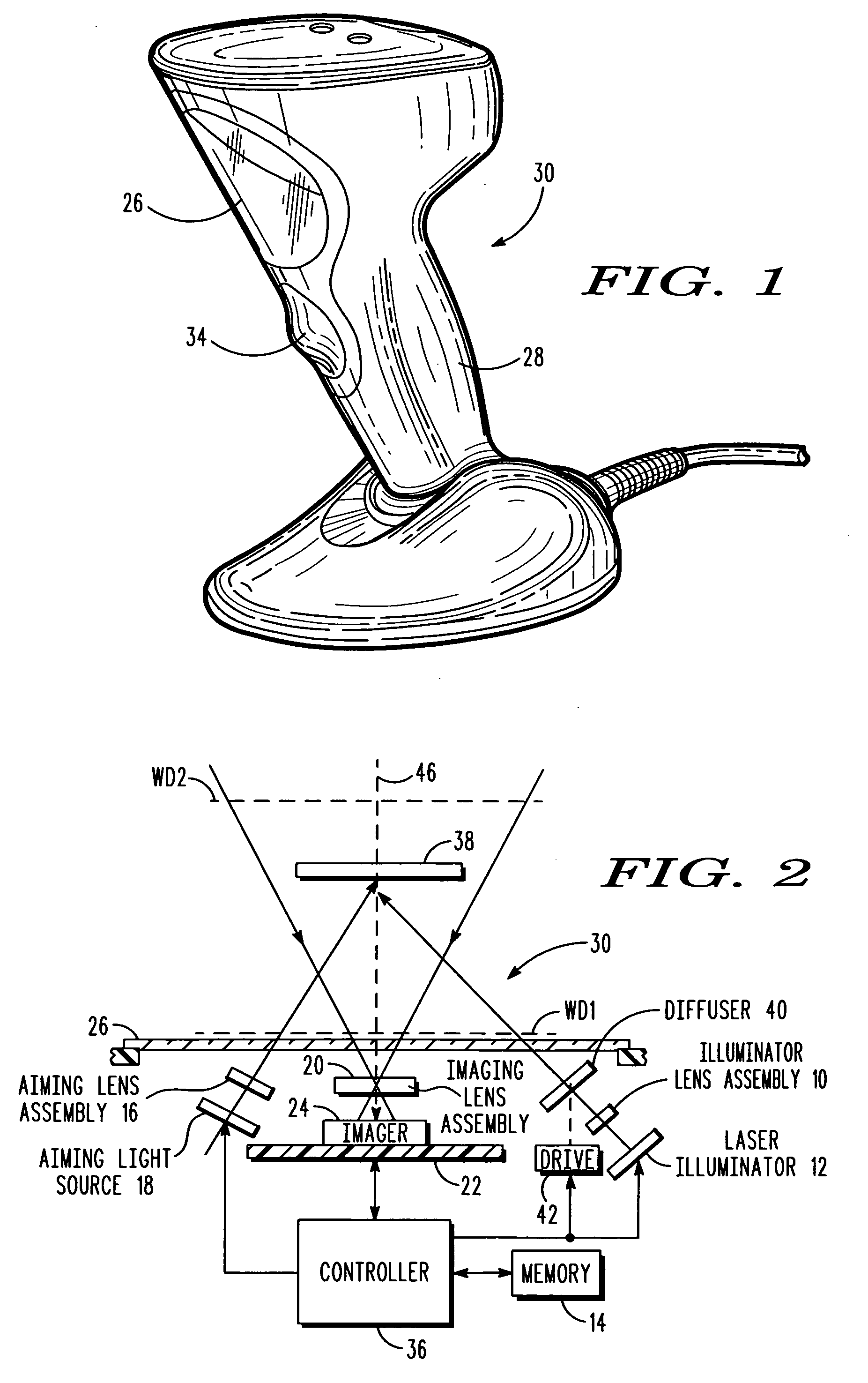
[0009]In accordance with this invention, the efficiency of the illuminating light and the range of working distances for the imaging reader has been increased due to the use of the illuminating laser whose bright, intense, diffraction limited light, as compared to LED light, enables more return light to be detected by the imager. Yet, the inherent problem of speckle noise introduced by the illuminating laser is minimized by the moving diffuser, which changes the phase relationship of the illuminating laser beam, and causes averaging of different speckle patterns on the imager.

Problems solved by technology

Yet, the inherent problem of speckle noise introduced by the illuminating laser is minimized by the moving diffuser, which changes the phase relationship of the illuminating laser beam, and causes averaging of different speckle patterns on the imager.

Method used


Image

  • Imaging reader with efficient laser illumination
  • Imaging reader with efficient laser illumination

Examples


Embodiment Construction

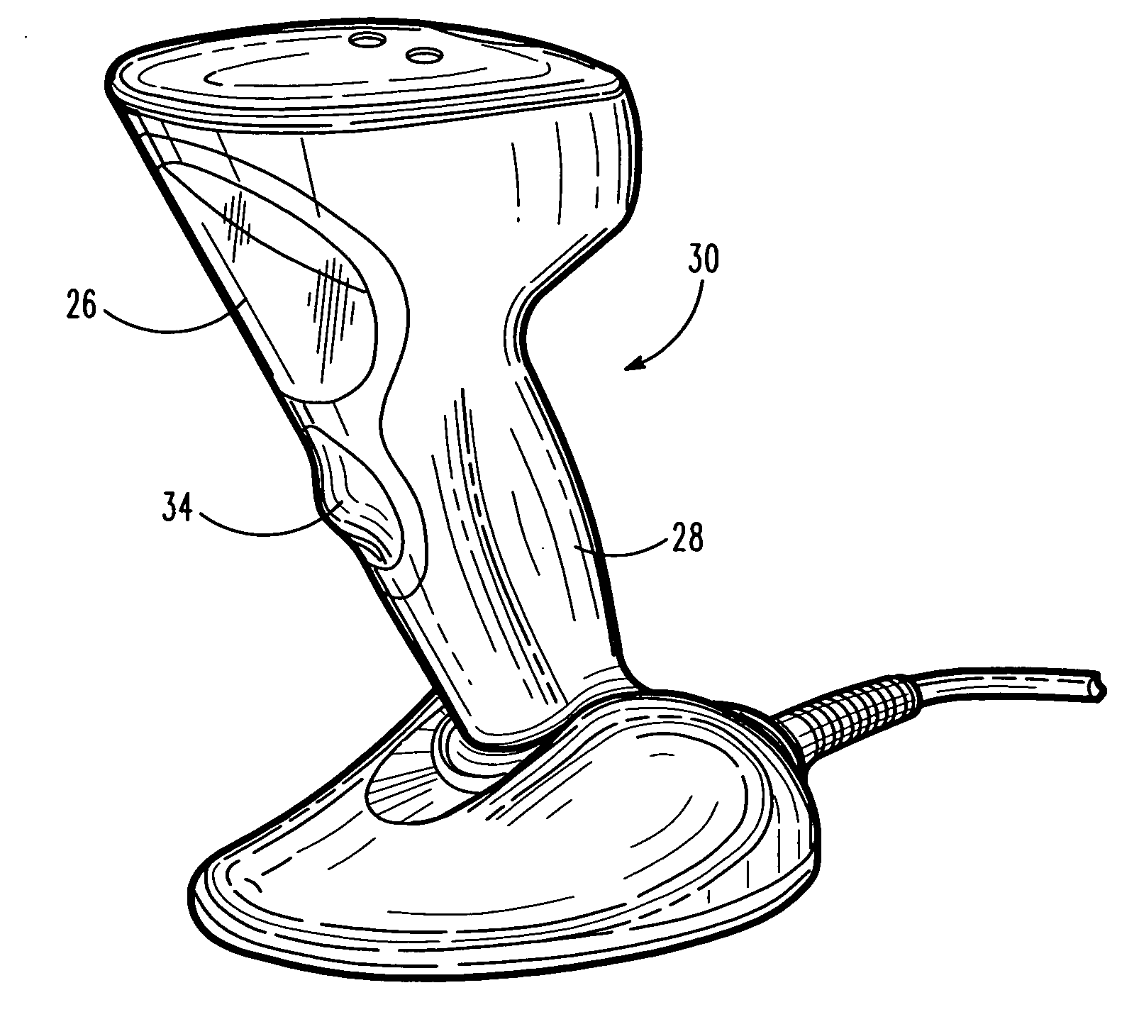
[0014]Reference numeral 30 in FIG. 1 generally identifies an imaging reader having a generally vertical window 26 and a gun-shaped housing 28 supported by a base 32 for supporting the imaging reader 30 on a countertop. The imaging reader 30 can thus be used in a hands-free mode as a stationary workstation in which products are slid, swiped past, or presented to, the vertical window 26, or can be picked up off the countertop and held in an operator's hand and used in a handheld mode in which a trigger 34 is manually depressed to initiate imaging of indicia, especially one-dimensional symbols, to be read at far distances from the window 26. In another variation, the base 32 can be omitted, and housings of other configurations can be employed. A cable, as illustrated in FIG. 1, connected to the base 32 can also be omitted, in which case, the reader 30 communicates with a remote host by a wireless link, and the reader is electrically powered by an on-board battery.

[0015]As schematically...


PUM


Abstract

An imaging reader for, and a method of, electro-optically reading a symbol by image capture employ an illuminating assembly that includes a laser for directing an illuminating laser beam along a path to the symbol to illuminate the symbol during image capture, a diffusing assembly that includes a movable diffuser in the path of the illuminating laser beam to diffuse the illuminating laser beam as diffused illuminating laser light, and a solid-state imager that includes an array of image sensors for capturing the diffused illuminating laser light returned from the symbol in a range of working distances over a field of view.

Description

DESCRIPTION OF THE RELATED ART[0001]Solid-state imaging systems or imaging readers, as well as moving laser beam readers or laser scanners, have both been used to electro-optically read targets, such as one-dimensional bar code symbols, particularly of the Universal Product Code (UPC) type, each having a row of bars and spaces spaced apart along one direction, as well as two-dimensional symbols, such as Code 49, which introduced the concept of vertically stacking a plurality of rows of bar and space patterns in a single symbol, as described in U.S. Pat. No. 4,794,239. Another two-dimensional code structure for increasing the amount of data that can be represented or stored on a given amount of surface area is known as PDF417 and is described in U.S. Pat. No. 5,304,786.[0002]The imaging reader includes an imaging module having a solid-state imager with a sensor array of cells or photosensors, which correspond to image elements or pixels in a field of view of the imager, and an imagin...

Claims


Application Information

Patent Timeline
IPC IPC(8): G06K7/10
CPCG06K7/10722
Inventor STERN, MIKLOS
Owner SYMBOL TECH INC
Learn More