Optical element and spectroscopic device using the same

a technology of optical elements and spectroscopic devices, applied in the direction of optical radiation measurement, polarising elements, instruments, etc., can solve the problem that the size of the device cannot but become larg

Inactive Publication Date: 2006-03-07
NIPPON SHEET GLASS CO LTD
View PDF8 Cites 0 Cited by
  • Summary
  • Abstract
  • Description
  • Claims
  • Application Information

AI Technical Summary

Benefits of technology

[0109]The simplest structure of the multilayer film is obtained when two layers physically equal in thickness to each other are formed in one period. Demultiplexing characteristic, polarizing characteristic and efficiency of utilizing input light can be improved when the average refractive index and the band structure are adjusted by the following means:
[0110](1) means for changing the thickness ratio between the two layers;
[0111](2) means for providing three or more layers; and
[0112](3) means for providing three or more kinds of film materials.
[0113]Even in the case where each of layers constituting the multilayer film has a refractive index changing continuously, the characteristic of the multilayer film can be substantially kept constant if the refractive index difference is kept constant.
[0114]The material of the substrate is not particularly limited if transparency can be obtained surely in a used wavelength range. Examples of the material preferably used include soda-lime glass, optical glass, silica, silicon, and compound semiconductor such as gallium arsenide. A plastic material may be also used if there is little limitation in temperature characteristic or the like.

Problems solved by technology

Hence, there is a problem that device size cannot but become large in order to improve the performance of the optical demultiplexer using the diffraction grating.

Method used


Image

  • Optical element and spectroscopic device using the same
  • Optical element and spectroscopic device using the same
  • Optical element and spectroscopic device using the same

Examples


example 1

CALCULATION EXAMPLE 1

[0151]In Calculation Example 1, the medium A was made of air, the medium B was made of a substrate (n=1.44), and the multilayer film had a structure simply constituted by two kinds of layers. One period of the multilayer film was constituted by two layers equal in thickness to each other. The refractive indices of the two layers were 3.48 and 1.44 respectively.

[0152]According to results of band calculation (FIG. 22) using a plane wave method, effective refractive indices for the first and third band light rays propagated through the periodic structural portion are 3.23 and 1.17 respectively. It is predictable that the following result can be obtained.

[0153]Medium A (air) side: no refracted light generated

[0154]Medium B (substrate) side: third band refracted light generated (θ=35.7°)

[0155]FIG. 23 shows a result of simulation. Refracted light having an angle θ of about 33° is generated on the medium B side from the multilayer structural portion. This substantially...

example 2

CALCULATION EXAMPLE 2

[0156]The condition for Calculation Example 2 is substantially the same as that for Calculation Example 1 except that the refractive index of a layer abutting on the medium A (air) is 1.44. Results of band calculation are equivalent to that shown in FIG. 22.

[0157]FIG. 24 shows a result of simulation. Refracted light having an angle θ of about 33° is generated on the medium B side from the multilayer structural portion. This substantially agrees with the prediction based on the band calculation. The same result as obtained in Calculation Example 1 can be obtained.

example 3

CALCULATION EXAMPLE 3

[0163]The condition for Calculation Example 3 is substantially the same as that for Calculation Example 1 except that the wavelength of input light is 1.987a. Results of band calculation are equivalent to that shown in FIG. 22.

[0164]Effective refractive indices for the first and third band light rays propagated through the periodic structural portion are 3.167 and 0.704 respectively. It is predictable that the following result can be obtained.

[0165]Medium A (air) side: third band refracted light generated (θ=45.3°)

[0166]Medium B (substrate) side: third band refracted light generated (θ=60.7°)

[0167]FIG. 26 shows a result of simulation. Refracted light having an angle θ of about 42° is generated on the medium A side from the multilayer structural portion whereas refracted light having an angle θ of about 59° is generated on the medium B side from the multilayer structural portion. This substantially agrees with the prediction based on the band calculation.


PUM


Abstract

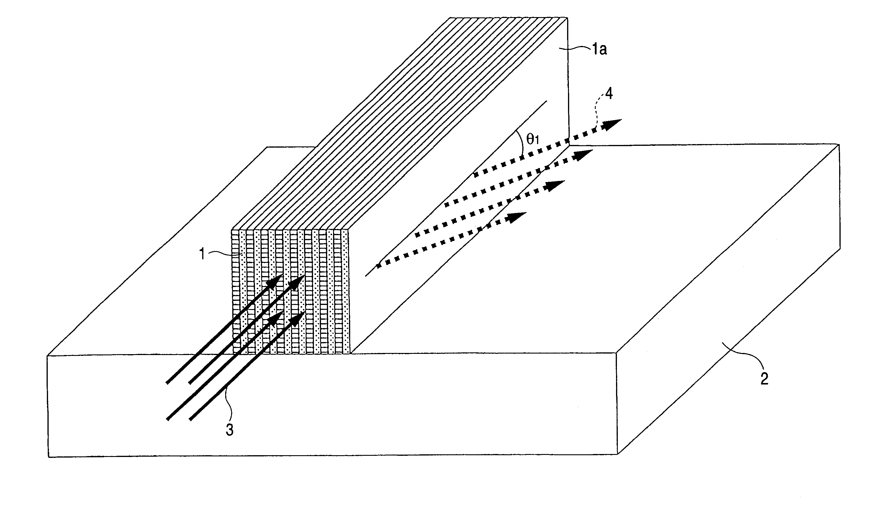
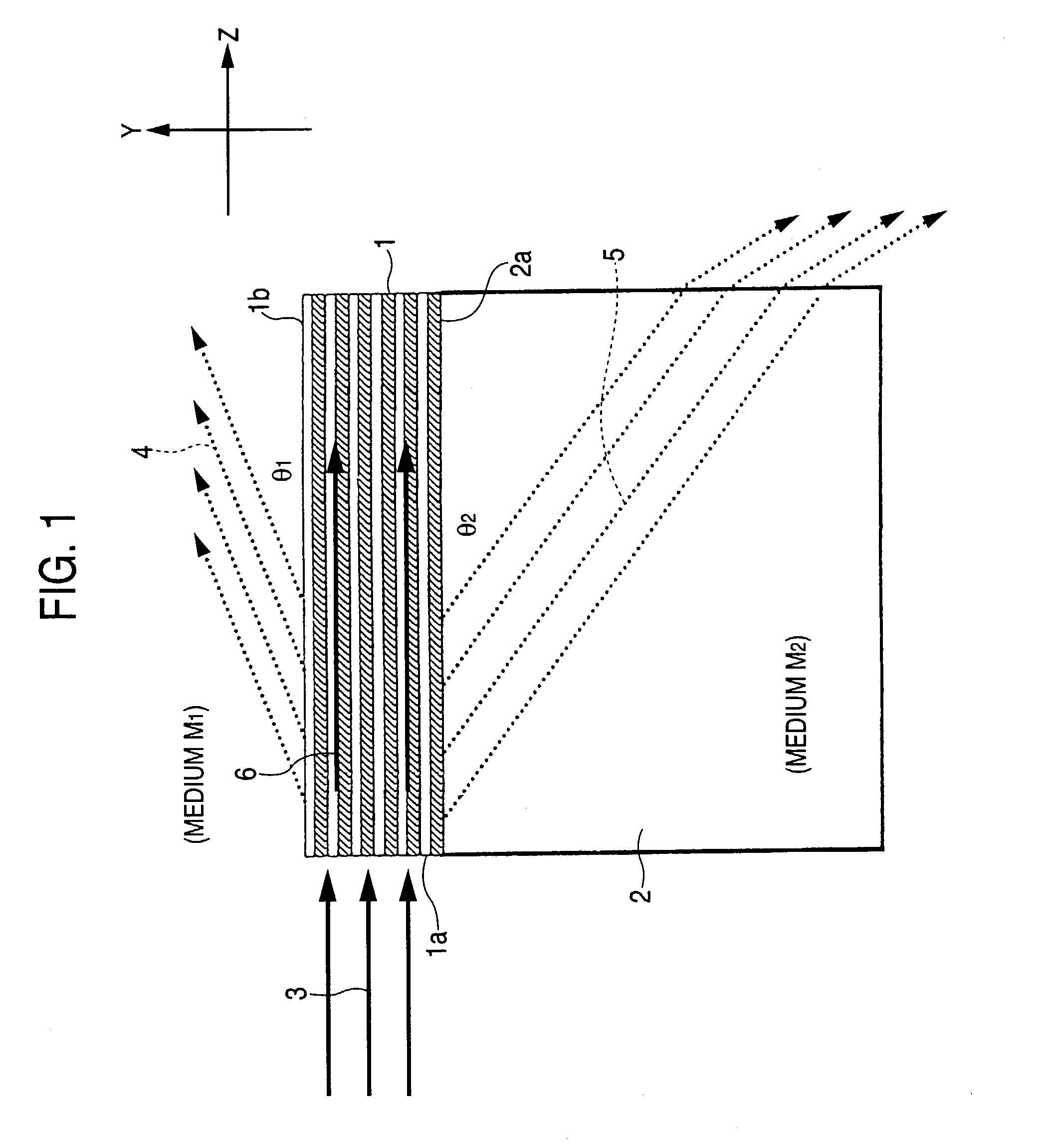
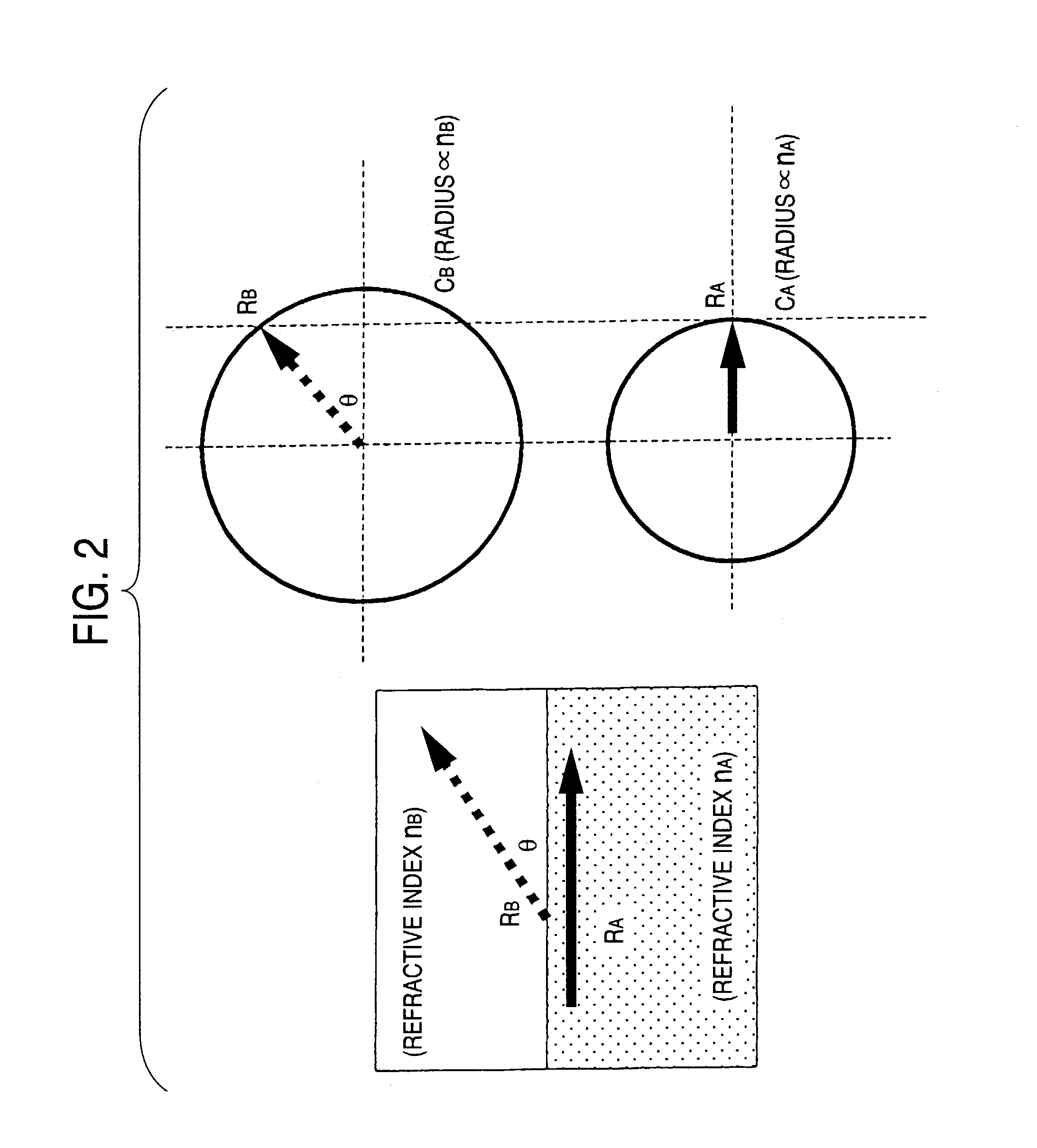
An optical element according to the invention constituted by a multilayer structure having a periodic structural portion as at least one region constituted by repetition of a predetermined period, wherein an end surface of the multilayer structure not parallel to layer surfaces of the multilayer structure is used as a light input surface whereas one or each of opposite surfaces of the multilayer structure parallel to the layer surfaces is used as a light output surface. There is an intermediate layer between a medium and a surface of the multilayer structure, the intermediate layer having a refractive index less than the refractive index of the medium. The periodic structural portion of the multilayer structure can be regarded as a one-dimensional photonic crystal. Refracted light from the one-dimensional photonic crystal has good directivity and the direction of the refracted light has strong dependence on wavelength. When this wavelength dependence property is used, a spectroscopic device or a polarized light separating device of high resolution can be achieved without increase in device size.

Description

BACKGROUND OF THE INVENTION[0001]The present invention relates to an optical element and a spectroscopic device for use in an optical communication system, an optical measuring instrument, etc.[0002]Increase in capacity of an optical fiber communication network has been intensely demanded with the rapid advance of popularization of the Internet in recent years. Development of WDM (wavelength division multiplexing) communication as means for increasing the capacity has been advanced rapidly. In WDM communication, optically functional elements such as an optical demultiplexer, a filter and an isolator excellent in wavelength selectivity are required because various kinds of information are transmitted individually by light having slightly different wavelengths. It is a matter of course that mass production, miniaturization, integration, stability, etc. are strongly required of the functional elements.[0003]An optical demultiplexer (or a spectroscopic device) is used for demultiplexing...

Claims


Application Information

Patent Timeline
Patent Type & Authority Patents(United States)
IPC IPC(8): G01J3/28G01J3/14G02B5/18G02B5/30G02B6/12G02B6/122G02B6/34
CPCB82Y20/00G02B6/29362G02B6/1225
Inventor KITTAKA, SHIGEONARA, MASATOSHINAKAZAWA, TATSUHIROOYA, KAZUAKITSUNETOMO, KEIJI
Owner NIPPON SHEET GLASS CO LTD
Why Eureka
Try Eureka