
Integrating Cone for an Illumination Device

a technology of illumination device and integrated cone, which is applied in the field of illumination, can solve the problems of inefficient electro-optical efficiency, low power of direct light emitting diodes or laser diodes in this range, and insufficient efficiency of solid-state lighting, etc., and achieve the effect of increasing the optical power and coupling efficiency of a solid-state light sour

Active Publication Date: 2017-06-08
EXCELITAS CANADA
View PDF4 Cites 0 Cited by
  • Summary
  • Abstract
  • Description
  • Claims
  • Application Information

AI Technical Summary

Benefits of technology

The present invention is an integrating cone for an illumination device that increases the optical power and coupling efficiency of a solid state light source in the green and / or yellow bands. It has a recess with a surface that reflects visible light with Lambertian scatter characteristics. This device improves the brightness and quality of illumination.

Problems solved by technology

Direct light emitting diodes (LEDs) or laser diodes in this range are traditionally very low powered and / or inefficient from an electro-optical perspective.
This issue with solid state lighting producing light at wavelengths in the green / yellow / amber range is fundamentally limited by the physics of the semiconductor materials used in the construction of these devices, as the band-gap of the materials does not favor emission of light in this spectral range.
However, existing solid state apparatuses and methods for generating green light that meets optical power requirements for fluorescence imaging applications are generally costly.
The conventional approach has been either devices having low output in the green-yellow band or low coupling efficiency for large area LEDs.
LED array or laser pumped crystal or phosphor solutions are relatively expensive compared to arc lamps for some applications with low cost requirements.
Thus, the power delivered to the microscope objective plane cannot typically be increased by simply increasing the LED surface area (it is an Etendue limited optical system).
The efficiency of such a device is limited by the total internal reflection of such a luminescent material due to its high index of refraction, and more importantly, coupling from LED to crystal.
This results in a need of a large number of LEDs to achieve the brightness needed, which increases cost, size, and thermal / electrical requirements on systems employing this method.
This approach is very effective in producing a scalable amount of power in the green / yellow band but can be costly.
The particular shape and size of the crystal, multiple laser diodes, and cooling methods lead to increased assembly and manufacturing costs.
Other combinations of lasers and phosphors have also been suggested for many high brightness applications including fluorescence illumination, such as U.S. patent application Ser. No. 13 / 897,237, and other applications such as automotive headlights, for example, U.S. patent application Ser. No. 13 / 697,782, and digital projection systems, such as U.S. patent application Ser. No. 13 / 942,603, but these methods are still unable to meet the same cost targets as mercury or xenon arc lamps, which are currently the industry standard.

Method used


Image

  • Integrating Cone for an Illumination Device
  • Integrating Cone for an Illumination Device
  • Integrating Cone for an Illumination Device

Examples


first embodiment

[0027]There is competition to provide a basic solid state lighting (SSL) illumination system, and many systems on the market today still do not offer the performance of the traditional arc lamp systems. The first embodiment, described below, approaches an arc lamp system, such as the X-Cite 120 for example, in terms of performance and cost.

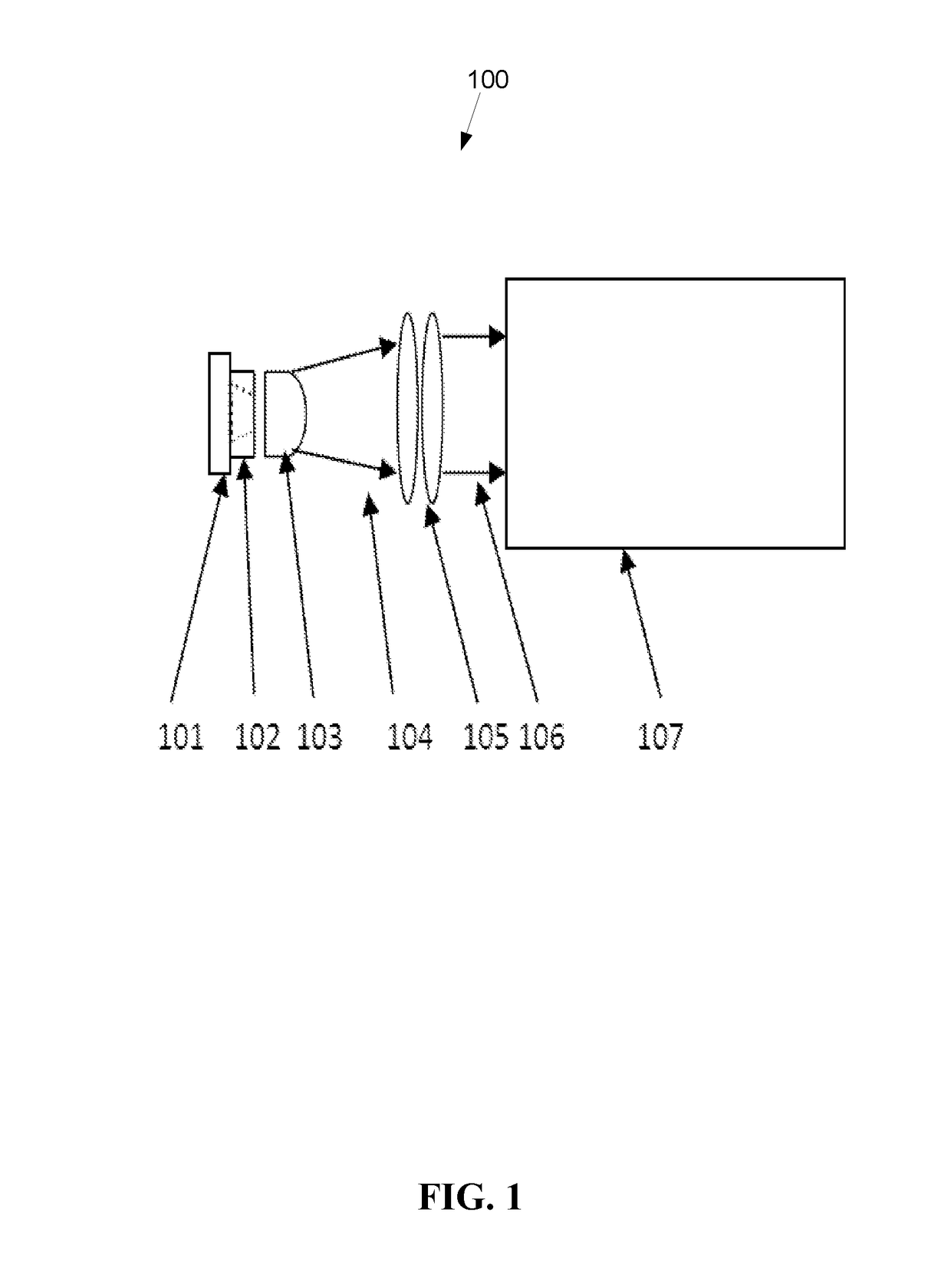
[0028]FIG. 1 is a schematic diagram of a first embodiment of an illumination system 100 with increased optical power in the green band. The overall optical layout is generally typical for a microscopy illumination system, however, as described below, the first embodiment includes features not present in previous systems.

[0029]A conventional large area white LED 101, for example, having an emitting area greater than 9 mm2, is low cost and may utilize a phosphor layer deposited on a blue or UV LED to create a broadband white light spectrum, for example, Luminius CBT-140. Although the power output of such a large LED 101 is relatively high compared t...

second embodiment

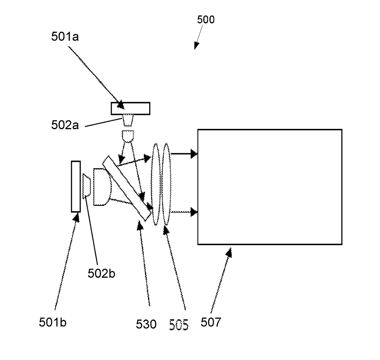
[0042]FIG. 5 is a schematic diagram of an illumination system 500 with increased optical power in the green band. As shown in FIG. 5, the illumination system 500 may include multiple LED light sources 501, where integrating cones 502a, 502b may be coupled with one or more of the multiple LEDs 501a, 501b. The LEDs 501a, 501b may have different properties, for example, producing light having of different wavelengths, different beam sizes, and / or different power characteristics. The light of the LEDs 501a, 501b and integrating cones 502a, 502b may be combined by a blending means 530, for example, a prism or dichroic plates. After light of multiple LED sources 501a, 501b is combined by the blending means 530, the combined light may be collimated by a collimating lens 505. The collimated beam may be coupled to a microscopy system 507. While FIG. 5 shows two LEDs 501a, 501b and two integrating cones 502a, 502b, alternative embodiments may have two, three, or more LEDs, and two, three or m...

third embodiment

[0043]As shown in FIG. 6, under an optical system 600, one or more integrating cones 602a, 602b can also be used in light guide coupled applications to increase the green optical power coupled to a light guide 606. The light of the LEDs 601a, 601b and integrating cones 602a, 602b may be combined by blending means 630. Collimated light from a collimating lens 604 is coupled to the light guide 606 by using a focus lens 605. The output of the light guide 606 may be collimated and coupled to a microscopy system 607 by an optical lens system 610. The blending means 630 may include one or more dichroic filters / plates. The blending means 630 may also blend in light from light sources in addition to or instead of LED 601a, which may or may not incorporate one or more additional integrating cones.

[0044]FIG. 7 is a flowchart of an exemplary method 700 for increasing the optical power of a solid state light source with a phosphor layer in the green and / or yellow bands for improved fluorescence...


PUM

PropertyMeasurementUnit
peak wavelengthaaaaaaaaaa
radiusaaaaaaaaaa

Abstract

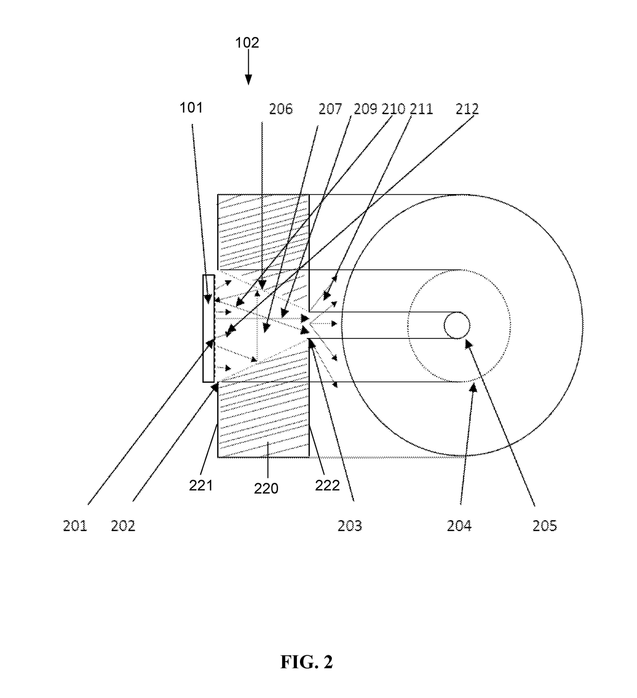
A device for increasing the optical power of a solid state light source in the green and / or yellow bands, is disclosed. The device has an integral body having an ingress surface configured to receive light from an emitting portion of the solid state light source, an egress surface substantially opposite the ingress surface, and a recess formed within the body. The recess has an input opening in the ingress surface, an output opening in the egress surface, and a recess surface within the body extending between the input opening and the output opening. The recess surface is configured to reflect visible light with Lambertian scatter characteristics.

Description

CROSS-REFERENCE TO RELATED APPLICATION[0001]This application is a divisional application of, and claims priority to, U.S. application Ser. No. 14 / 691,987 entitled Integrating Cone for an Illumination Device, which was filed on Apr. 21, 2015, the disclosure of which is incorporated herein by reference in its entirety.FIELD OF THE INVENTION[0002]The present invention relates to illumination, and more particularly, is related to solid state illumination devices.BACKGROUND OF THE INVENTION[0003]Solid state technology has progressed very far in recent decades. However there is still significant room for improvement in the green / yellow / amber range of the electromagnetic spectrum, approximately 520-600 nm. Direct light emitting diodes (LEDs) or laser diodes in this range are traditionally very low powered and / or inefficient from an electro-optical perspective. This issue with solid state lighting producing light at wavelengths in the green / yellow / amber range is fundamentally limited by the...

Claims


Application Information

Patent Timeline
Patent Type & Authority Applications(United States)
IPC IPC(8): G02B21/08F21V13/14F21V7/22F21V5/04G01N21/64G02B21/16G02B27/14G02B19/00G02B27/10F21V9/16F21V8/00
CPCG02B21/08G01N2021/6478F21V13/14F21V7/22F21V5/04G02B6/0001G02B21/16G02B27/141G02B19/0019G02B19/0061G02B19/0095G02B27/1006G01N21/6458F21Y2115/10F21Y2113/13G01N2021/6471F21V9/16F21V9/30F21V13/08G02B27/0994G02B17/004
Inventor WANG, YONGCONSTANTINOU, PAULKUK, SOLA ANNE
Owner EXCELITAS CANADA
Learn More