Ac light emitting diode

a light-emitting diode and ac technology, applied in the field of light-emitting diodes, can solve the problems of inability to continuously emit light, inability to use the light-emitting diode while connected directly, and easy damage, so as to reduce the flicker phenomenon of the ac light-emitting diode, reduce the turn-on and operating voltage, and increase the light-emitting time of the light-emitting diod

Active Publication Date: 2010-05-13
SEOUL VIOSYS CO LTD
View PDF1 Cites 70 Cited by
  • Summary
  • Abstract
  • Description
  • Claims
  • Application Information

AI Technical Summary

Benefits of technology

[0009]Another object of the present invention is to provide an AC light emitting diode in which light emitting cells are arranged within a chip of a limited size such that excellent operating characteristics and light outputs can be secured at the chip level.
[0010]A further object of the present invention is to provide an AC light emitting diode capable of preventing overvoltage from being applied to a specific light emitting cell during operation.
[0015]Furthermore, at least one shunt wire may electrically connect corresponding wires of the first and second serial arrays operably connected in reverse parallel to each other. The shunt wire prevents overvoltage from being applied to a specific light emitting cell in the serial array to which reverse voltage is applied when the AC light emitting diode is operated.
[0017]In addition, a transparent electrode layer may be formed on the second conductive type semiconductor layer of each of the light emitting cells. The transparent electrode layer allows current to be uniformly distributed over the second conductive type semiconductor layer and light generated in the active layer to be radiated upward through the second conductive type semiconductor layer.
[0020]According to the present invention, an AC light emitting diode capable of being continuously operated while connected to an AC power source can be provided. Further, spacing distances between light emitting cells are set within a range of 10 to 30 μm, and thus, turn-on and operating voltages can be lowered to thereby increase the light emitting time of the light emitting diode under AC power source. Accordingly, an amount of light emitted from the light emitting diode can be increased, and a flicker phenomenon of the AC light emitting diode can be reduced. Furthermore, since the light emitting cells are arranged at a spacing distance of 10 μm or more, the light emitting cells can be easily separated from one another, wires for connecting the light emitting cells to one another can be easily formed, and a short circuit occurring between the wires can be prevented. In addition, since the light emitting cells are arranged at a spacing distance of 30 μm or less, an etching time required to form the light emitting cells can be reduced and the etching damage which may be induced to the light emitting cells can also be reduced.

Problems solved by technology

Thus, when a light emitting diode is used while connected directly to an AC power source, it cannot continuously emit light and may be easily damaged due to reverse current.
Further, such a light emitting diode cannot be used while connected directly to a general AC power source, due to low operating voltage.
However, the necessity of such a rectifier makes it difficult to substitute a light emitting diode for a lighting system such as a fluorescent lamp.
However, since a large number of light emitting diodes should be operated while connected with one another, the overall size of a light emitting device is increased.

Method used


Image

  • Ac light emitting diode
  • Ac light emitting diode
  • Ac light emitting diode

Examples


Embodiment Construction

[0026]Hereinafter, preferred embodiments of the present invention will be described in detail with reference to the accompanying drawings. The following embodiments are provided only for illustrative purposes to fully convey the spirit of the present invention to those skilled in the art. Therefore, the present invention is not limited to the following embodiments but may be implemented in other forms. In the drawings, the widths, lengths, thicknesses and the like of elements are exaggerated for convenience of illustration Like reference numerals indicate like elements throughout the specification and drawings.

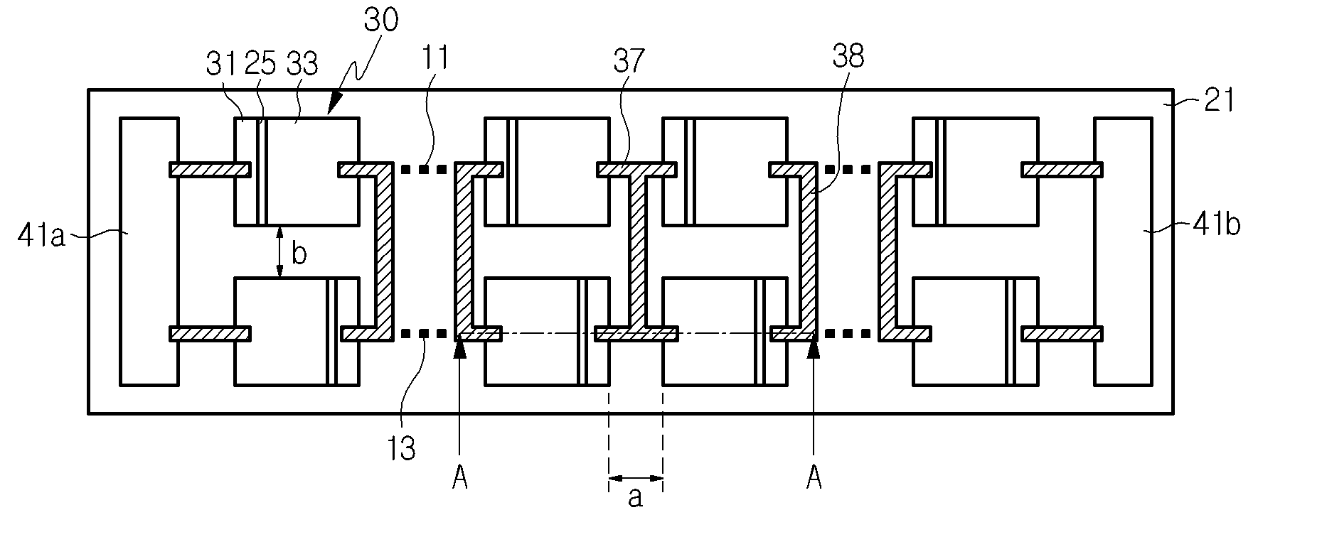
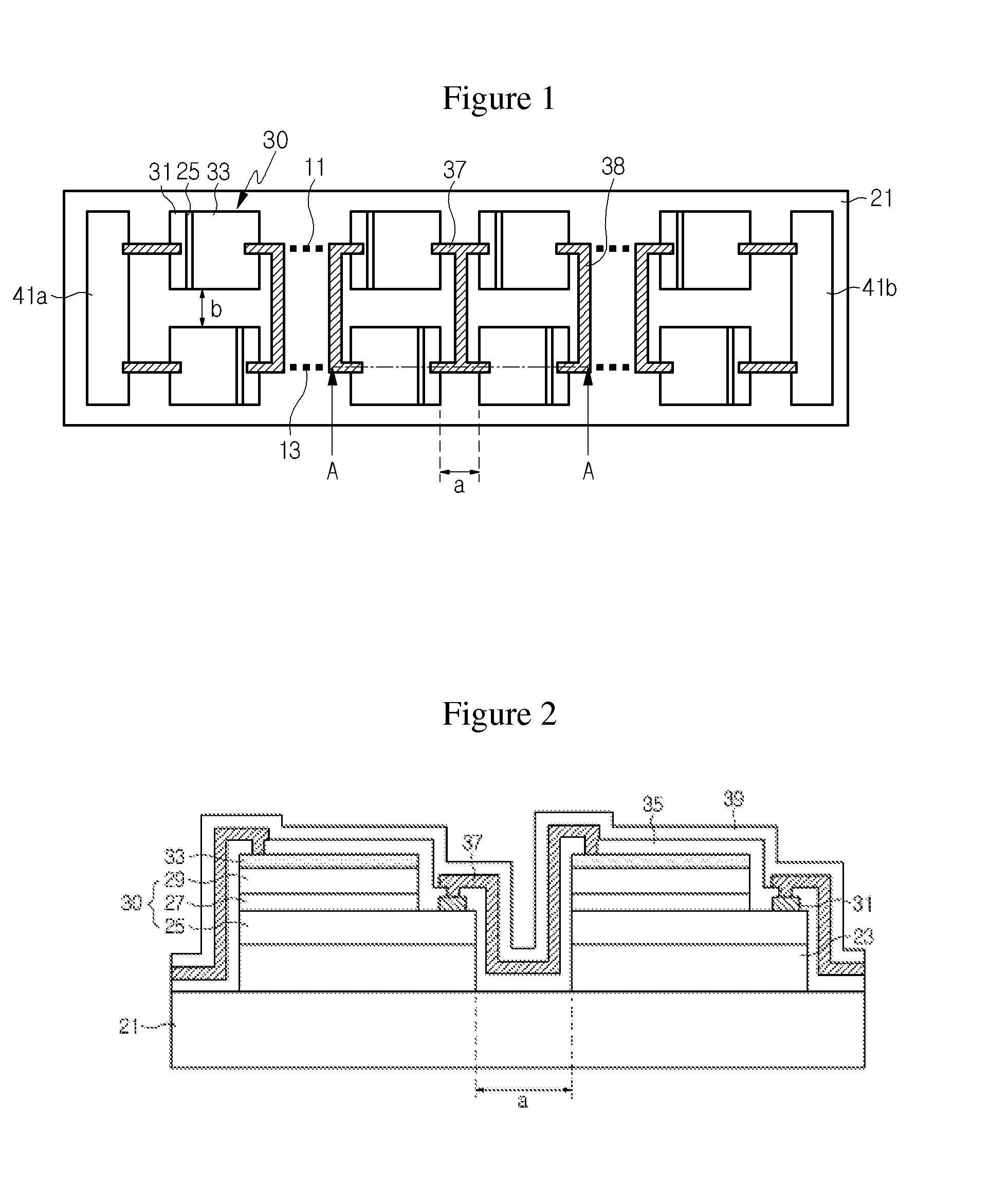
[0027]FIG. 1 is a plan view illustrating an AC light emitting diode according to an embodiment of the present invention, and FIG. 2 is a sectional view taken along line A-A in FIG. 1.

[0028]Referring to FIGS. 1 and 2, a plurality of light emitting cells 30 are arranged on a substrate 21. The substrate 21 generally has a limited size, e.g. a size of 2000×2000 μm2 or less. The si...


PUM


Abstract

Disclosed herein is an AC light emitting diode. The light emitting diode comprises a plurality of light emitting cells two-dimensionally arranged on a single substrate. Wires electrically connect the light emitting cells to one another to thereby form a serial array of the light emitting cells. Further, the light emitting cells are spaced apart from one another by distances within a range of 10 to 30 μm, and the serial array is operated while connected to an AC power source. Accordingly, the excellent operating characteristics and light output power can be secured in an AC light emitting diode with a limited size.

Description

CROSS REFERENCE TO RELATED APPLICATION[0001]This application is a continuation of U.S. application Ser. No. 12 / 515,869 filed on May 21, 2009, which is the National Stage of International Application No. PCT / KR2007 / 001215, filed Mar. 13, 2007, which are hereby incorporated by reference for all purposes as if fully set forth herein.BACKGROUND OF THE INVENTION[0002]1. Field of the Invention[0003]The present invention relates to a light emitting diode, and more particularly, to an AC light emitting diode capable of being operably connected directly to an AC power source.[0004]2. Discussion of the Background[0005]Light emitting diodes are an electroluminescence device having a structure in which n-type and p-type semiconductors are joined together, and emit predetermined light through recombination of electrons and holes. Such light emitting diodes have been used as display devices and backlights. Further, since the light emitting diodes have less electric power consumption and a longer ...

Claims


Application Information

Patent Timeline
Patent Type & Authority Applications(United States)
IPC IPC(8): H01L33/00H01L33/08H01L33/62
CPCH01L27/15H01L33/62H01L2224/48137H01L2224/48091H01L2924/00014H01L33/08
Inventor KIM, DAE WONYOON, YEO JINKAL, DAE SUNG
Owner SEOUL VIOSYS CO LTD
Why Eureka
Try Eureka