
LED with light-conversion layer

a technology of led light and conversion layer, which is applied in the direction of electrical equipment, semiconductor/solid-state device manufacturing, and semiconductor devices, etc., can solve the problems of difficult optimization of led-based lighting devices, many limitations, and insufficient brightness of white light sources, etc., and achieve the effect of maximizing yellow light outpu

Inactive Publication Date: 2010-05-13
LEDENGIN
View PDF62 Cites 71 Cited by
  • Summary
  • Abstract
  • Description
  • Claims
  • Application Information

AI Technical Summary

Benefits of technology

[0010]Accordingly, it would be desirable to provide cost-effective LED-based lighting sources having improved efficiency and brightness. Such improvement will allow for devices with smaller packages and higher luminosities, which are critical for many light source applications.
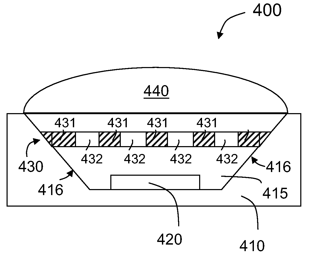
[0017]According to another embodiment of the present invention, a lighting apparatus includes a blue light-emitting diode and a light-conversion layer overlying the light-emitting diode. The light-conversion layer has a plurality of non-overlapping regions including one or more wave-shifting regions and one or more non-wave-shifting regions. The light-conversion layer is configured such that the lighting apparatus provides substantially uniform white light. The light-conversion layer can be in physical contact with the light-emitting diode, or spaced apart from the light-emitting diode. Alternatively, the light-conversion layer can be in direct contact with a lens in a top portion of the lighting apparatus. In some embodiments, the thickness of the light-conversion layer is selected to maximize yellow light output. Furthermore, the pattern of wave-shifting regions and non-wave-shifting regions can be designed for providing the desired ratio and distribution of yellow and blue light to produce substantially uniform white light.

Problems solved by technology

Even though conventional LED-based white light sources have found wide application, they suffer from many limitations.
One common problem is that conventional LED-based white light sources often do not provide sufficient brightness.
As described in more detail below, it is difficult to optimize LED-based lighting devices such that the light is both maximally bright and truly white.
While brightness can be increased by increasing operating voltage, this increases operating costs and thermal management requirements.

Method used


Image

  • LED with light-conversion layer
  • LED with light-conversion layer
  • LED with light-conversion layer

Examples


Embodiment Construction

[0037]In embodiments of the invention, various methods are provided for forming a lighting apparatus having a light-conversion layer. The methods allow for independent optimization of light conversion efficiency and proportion of light components having different colors. In a specific application, such a light-conversion layer can be used with a blue LED to produce uniform white light with improved brightness compared to conventional devices. But it will be recognized that the invention has a much broader range of applicability.

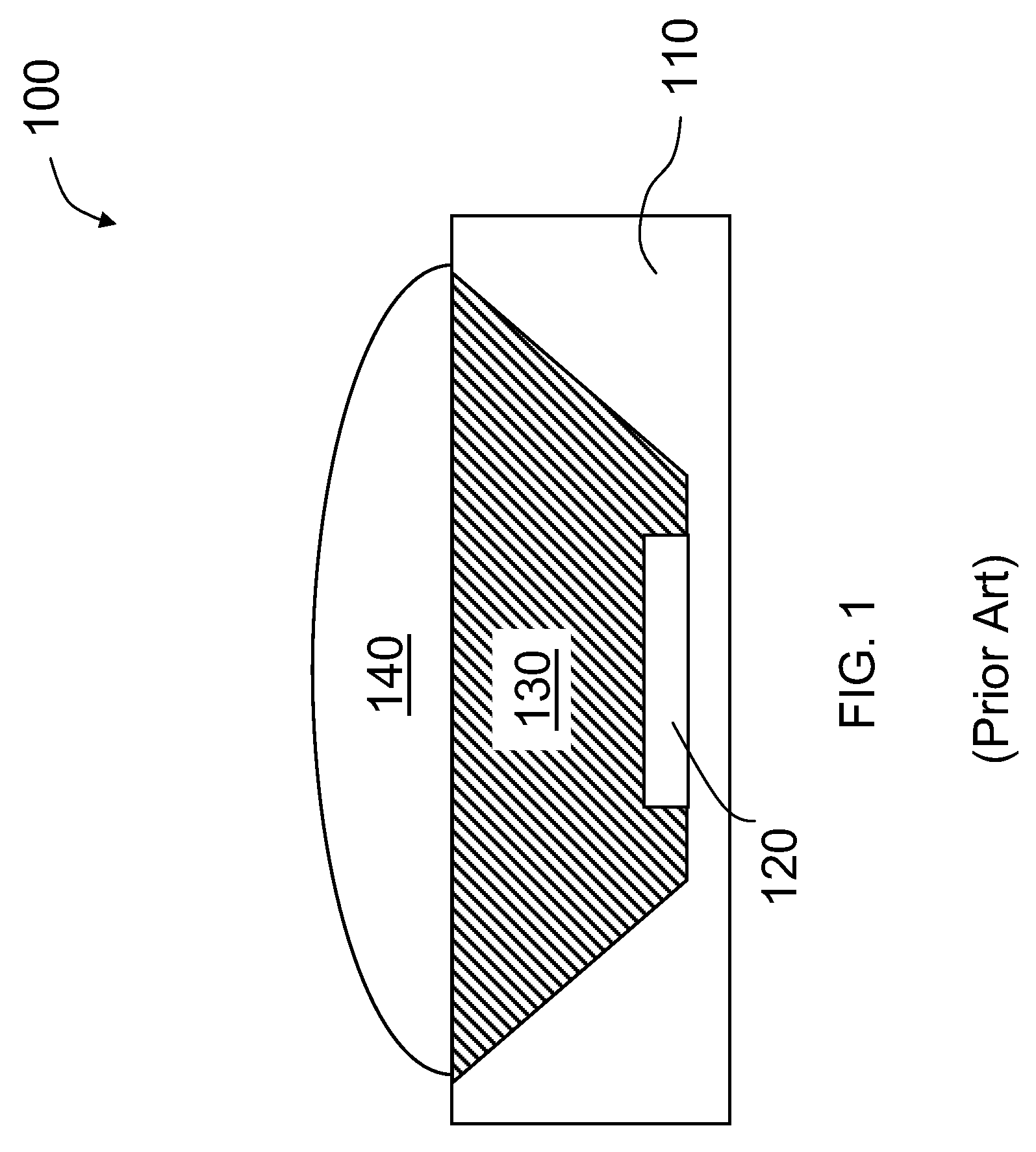
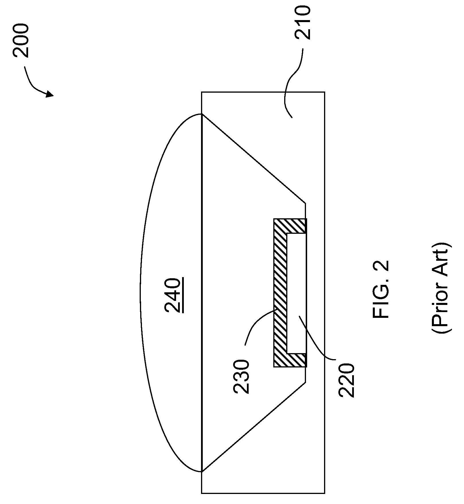
[0038]Before embodiments of the present invention are described in detail below, certain limitations of conventional white light LED devices are first analyzed. Two such conventional light emitting devices that incorporate phosphors are illustrated in FIGS. 1 and 2. FIG. 1 shows a schematic diagram of a light emitting device 100 having an LED 120 mounted on a substrate 110. As shown in FIG. 1, LED 120 is disposed at the bottom of a cavity in substrate 110. LE...


PUM


Abstract

A lighting apparatus includes a light-emitting diode (LED). A light-conversion layer having multiple non-overlapping regions overlies the light-emitting diode. The light-conversion layer includes at least one first region and at least one second region. In the lighting apparatus, the light-emitting diode is configured to emit light of a first color, the at least one first region is substantially transparent to light of the first color, and the at least one second region converts light of the first color to light of a second color. In an embodiment, the light-conversion layer is configured such that the lighting apparatus provides substantially uniform light of a third color. In some embodiments, the second region includes a phosphor-containing material, and the first region includes silicone or epoxy. In an example, the lighting apparatus uses a blue LED in conjunction with a yellow phosphor material to produce white light.

Description

CROSS-REFERENCES TO RELATED APPLICATIONS[0001]The application is related to U.S. patent application Ser. No. 11 / 036,559, filed on Jan. 13, 2005 and entitled “Light Emitting Device with a Thermal Insulating and Refractive Index Matching Material,” which is commonly owned and incorporated by reference herein.FIELD OF THE INVENTION[0002]The present invention relates generally to lighting apparatus and more particularly to methods and apparatus for providing enhanced brightness in light sources based on light-emitting diodes (LEDs).BACKGROUND OF THE INVENTION[0003]A light-emitting diode (LED) is a semiconductor device that produces light when an electric current is passed therethrough. LEDs have many advantages over conventional lighting sources, including compact size, low weight, longer life time, high vibration resistance, and higher reliability. In addition to having widespread applications for electronic products as indicator lights, LEDs also have become an important alternative l...

Claims


Application Information

Patent Timeline
IPC IPC(8): H01L33/00
CPCH01L33/508
Inventor TROTTIER, TROY A.
Owner LEDENGIN
Learn More