Portable renewable energy box system

a renewable energy and box system technology, applied in the direction of electric generator control, wind motor with solar radiation, machines/engines, etc., can solve the problems of large land and large available wind sources, and known towers that cannot be used for varying dynamic loads, etc., to dampen the vibration of the spinning turbine and add stability to the structure.

a renewable energy and box system technology, applied in the direction of electric generator control, wind motor with solar radiation, machines/engines, etc., can solve the problems of large land and large available wind sources, and known towers that cannot be used for varying dynamic loads, etc., to dampen the vibration of the spinning turbine and add stability to the structure.

US20100117369A1Inactive Publication Date: 2010-05-13MONOSTORY ERIK J

Image

  • Portable renewable energy box system
  • Portable renewable energy box system
  • Portable renewable energy box system

Examples


Embodiment Construction

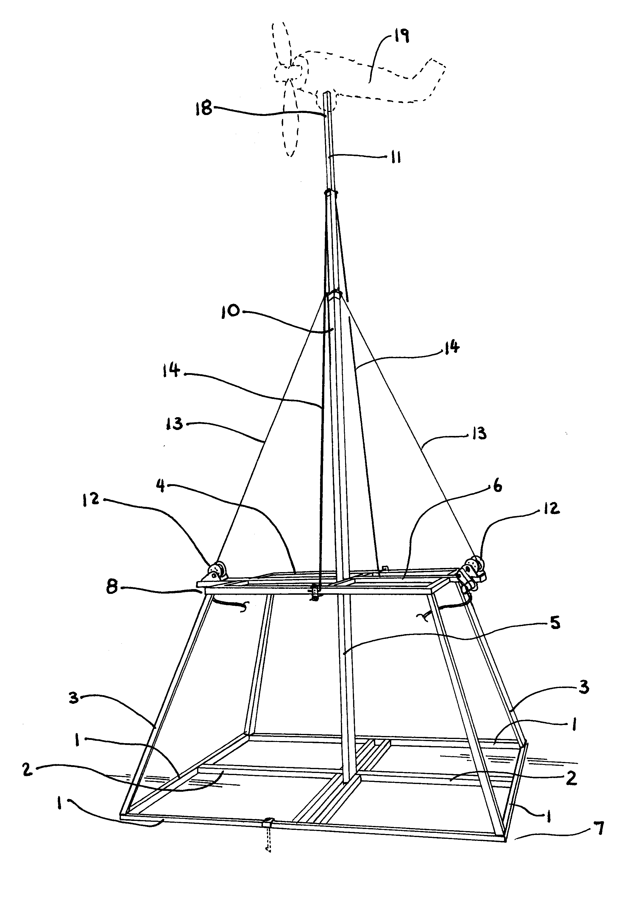
[0019]The renewable energy box system is a highly transportable and stable energy generating system that utilizes wind and solar power to produce electricity for homes, farms and other small energy consuming units.

[0020]The renewable energy box has a base in the shape of a square pyramid as shown in FIG. 1. A plurality of lower perimeter base rails 1 are connected to form an essentially square lower base 7. These perimeter base rails 1 are reinforced by inner reinforcing rails 2. The base is essentially square in the preferred embodiment, reinforced by the inner rails 2 as shown in FIG. 1.

[0021]Attached to the perimeter base rails 1 at each corner are vertical pyramidal risers 3. The pyramidal risers 3 slope upwardly and inwardly and connect the lower perimeter base rails 1 to the upper perimeter tower rails 4. These upper pyramidal tower rails 4 form a smaller essentially square upper tower support 8 to support the main mast 5. The upper tower rails 4 are interconnected and reinfor...


PUM


Abstract

A small, easily transportable wind turbine system has a square rail base secured to the ground by stakes and by its own weight. Slanted vertical legs connect a smaller square upper support perimeter to the base. A three-section telescoping mast is attached to the base and to the upper support. Winches and guy wires raise the second mast. As the second mast is raised, static guy wires raise the third mast. A wind generating turbine is attached to the top of the third mast. A controller senses the maximum output of the turbine and raises or lowers the height of the masts such that the minimum wind speed necessary to produce the maximum electric output is produced. The controller also feeds energy to a battery storage system and directly to a utility panel.

Description

BACKGROUND OF THE INVENTION[0001]This invention relates to the field of small, transportable electric power generators. In particular, a small, highly portable wind generator is presented that has an automatically extending and positioning mast.[0002]Energy is the largest economy in the world. The need to find energy sources independent of oil is a widely recognized and sought after goal. Wind and solar power have been recognized as good alternate energy sources. However, most wind generating systems require large amounts of land and large available wind sources. Wind generators in places such as Palm Springs and Sacramento California are examples of such large wind generator locations.[0003]The tower is one of the most significant parts of a wind generator. The three major types of towers are the guyed tower, the tilt-up tower and the self-supporting tower. Each type of tower needs a prefabricated foundation of reinforced concrete and each tower is permanently attached to the groun...

Claims


Application Information

Patent Timeline
13 May 2010
Publication
US20100117369A1
IPC
F03D11/04
CPC
F03D9/021; F03D11/04; F05B2220/61; Y02E70/10; F05B2240/9151; Y02B10/30; Y02E10/728; F05B2220/708
Inventors
MONOSTORY, ERIK J