Ink jet recording method and ink jet recording device

a recording device and inkjet printing technology, applied in the field of inkjet printing methods and inkjet printing apparatuses, can solve the problems of large amount of ink, difficulty in practice, uneven density, etc., and achieve the effects of reducing density unevenness, high speed, and increasing the amount of ejection

Inactive Publication Date: 2010-05-13
CANON KK
View PDF8 Cites 8 Cited by
  • Summary
  • Abstract
  • Description
  • Claims
  • Application Information

AI Technical Summary

Benefits of technology

[0055]In accordance with the present invention, the count and correction of image data within a single main scanning region enables a reduction of density unevenness in the same direction as the main scanning direction over a printing region, the variation occurring due to an increase in the ejection amount caused by a temperature increase of a printing head due to ink ejection. This makes it possible to perform high speed printing with deterioration in image quality being lessened.

Problems solved by technology

It is known that such temperature rise lowers the viscosity of the ink, and thereby causes a larger amount of ink to be ejected even by the driving under the same condition, which creates density unevenness.
Therefore, the management of temperature of the ink is strongly desired, but this is difficult in practice.
However, the sensor is attached in the vicinity of the head, and a precise output is not capable of being monitored with an MPU (CPU) due to a noise caused by a drive of the printing head, so that there have been problems that a precise temperature control is not capable of being made, and the controlling of an ejection amount is not sufficient.
However, this increases cost by that much.
High precision temperature estimation is achieved by shortening time intervals for a temperature estimation calculation, but the shortening of the time intervals increases a calculation load on a printing apparatus.
However, an increase in the drive frequency of the heater causes a rise of the temperature of the printing head to be marked, resulting in density unevenness due to an increase of the ejection amount.
Further, with dots having a small diameter, the number of dots printed on a printing region also increases, so that the density unevenness is further visible due to increase in the ejection amount of each nozzle.
Still further, when the next main scanning is performed with the temperature of the head remaining high due to the previous one-time main scanning, the ejection amount increases to a level higher than the level of any previous ejection amount, and density unevenness occurs for each main scanning.
In addition, even if the number of passes is reduced, the number of ink dots formed in one-time main scanning increases and therefore, in such a case also, an increase of the ejection amount due to an increase of the temperature of the printing head causes density unevenness on a printing region.
Further, when the drive frequency improvement and the pass number reduction are performed at the same time, it is natural that the influence thereof becomes considerably large.
Under such circumstances, a control which involves the detecting of the temperature of the printing head using a temperature sensor as conventional has a problem in responsiveness.
Therefore, when the detection of the temperature of the printing head is performed, or when the temperature estimation is performed on the basis of data to be printed, a controllable range of the ejection amount in a modulatable range of a pulse width is narrowed, so that controlling capability becomes insufficient.
Furthermore, especially, in a case of performing high speed printing, such as the case where bidirectional printing is applied in a one-pass printing mode, density unevenness may occur even within an region for a single main scanning.
None of the conventional techniques disclosed in Patent Documents 1 to 4 enables the controlling of effectively suppressing such density unevenness.

Method used


Image

  • Ink jet recording method and ink jet recording device
  • Ink jet recording method and ink jet recording device
  • Ink jet recording method and ink jet recording device

Examples


first embodiment

2.1 First Embodiment

[0106]FIG. 9 is a schematic view for explaining concepts of count areas, gradation values on each of which represented by pixel data are counted, and of printing areas, the number of printed dots on each of which is changed. In FIG. 9, for the sake of simplicity of description, printing areas are each assumed to have the same size as count areas.

[0107]As shown in FIG. 10, in this embodiment, for example, in the case where printing is performed on the whole printing area which is equivalent to one page of printing media in l=L, times of main scanning, inputted image data corresponding to print data for a single main scanning of an ejection portion are divided in a first scanning as follows. Specifically, input image data corresponding to data for (Number of nozzles)×(Number of dots on one line in the main scanning direction) are divided into N pieces (N=1 in FIG. 10) of count areas and printing areas in the longitudinal direction (nozzle arrangement direction), an...

second embodiment

3. Second Embodiment

[0149]A second embodiment of the present invention is described below. Incidentally, in this second embodiment, a basic configuration of a printing apparatus, a printing head, and a control system, and a printing mode are the same as those of the first embodiment. Further, in this embodiment, also, a relationship between temperature of a printing head and an ejection amount is as shown in the curve B of FIG. 8, and further, the printing head used in this embodiment has a characteristic that an increase in ejection amount is large with an increase in the temperature of a head compared with the increase in ejection amount in the first embodiment.

[0150]In this embodiment, as in the first embodiment, the method is used in which a total number of dots of image data, the data printing changes in the ejection amount, is changed, and also for the correction method of image data, the method in which multivalued data are changed is used. However, unlike the first embodimen...

example 1

4.1 Example 1

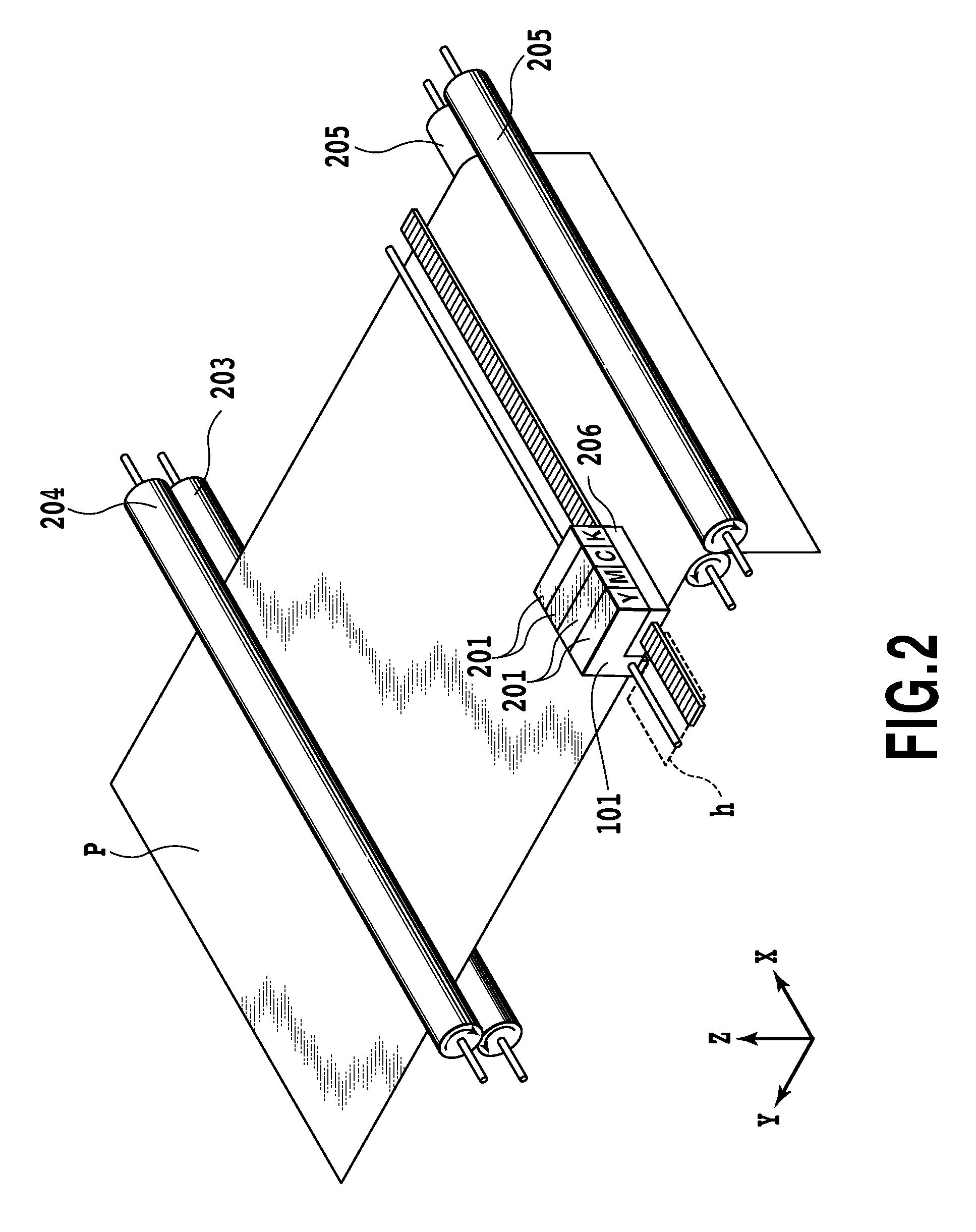
[0183]To Example 1, the same configurations as those of the foregoing printing apparatus (FIG. 2), printing head (FIG. 1), and control system (FIG. 6) are applied, and for the printing mode also, the one-pass printing mode is applied. In a case of using a printing head having an ejection portion provided with 256 nozzles arranged at a 1200 dpi (approximately 21.2 μm) pitch, printing with a printing swath of 256 / 1200 inches (approximately 5.42 mm) can be performed on a printing medium in a single main scanning. Further, in the one-pass printing mode, printing medium conveying (sub-scanning) is performed by an amount corresponding to the printing swath.

[0184]The printing head is one driven so that 3.0±0.5 pl of ink is ejected through each nozzle. For ink containing color material, a commercially available ink for an inkjet printer PIXSUS 860i (manufactured by Canon Inc.) was used. For a printing medium, A4 size glossy paper (Pro Photo Paper: PR-101 manufactured by Canon I...


PUM


Abstract

An inkjet printing apparatus, which ejects ink from a printing head to print, is provided for reducing an ejection amount increase caused by a temperature increase of the printing head due to ink ejection in the case of high speed printing, thereby suppressing density unevenness which occurs in a printing area in the main scanning direction due to the ejection amount increase. A scanning region of the printing head is divided into a plurality of count areas provided for counting the number of times of ink ejection based on image data and the count is carried out for each of the plurality of the counting areas. The scanning region of the printing head is divided into a plurality of printing areas provided for correcting the image data in response to the count value to print the image data and the correction of the image data is carried out for each of the plurality of the printing areas. In this way, the count of image data and their correction are carried out in one main scanning region.

Description

TECHNICAL FIELD[0001]The present invention relates to an inkjet printing method and an inkjet printing apparatus, and more particularly to an inkjet printing method and an inkjet printing apparatus for printing by causing an inkjet printing head to perform scanning over a printing medium such as a sheet of paper. Still more specifically, the present invention relates to a technique for reducing density unevenness on a printing medium in a main scanning direction.BACKGROUND ART[0002]An inkjet printing method is to eject inks onto a printing medium for printing from a printing portion including a printing head. When compared with other printing methods, the inkjet printing method has various advantages such as easiness of high definition and high speed printing as well as excellent quietness and inexpensiveness. In recent years, with an increase in the demand of color printing, various types of color inkjet printing apparatuses capable of printing in high image quality comparable to t...

Claims


Application Information

Patent Timeline
Patent Type & Authority Applications(United States)
IPC IPC(8): B41J29/38
CPCB41J2/04508G06K15/102B41J2/0458B41J2/04543
Inventor YAMAGUCHI, HIROMITSUSHIBATA, TSUYOSHI
Owner CANON KK
Why Eureka
Try Eureka