Method and apparatus for detecting defects and embedded objects in sealed sterilized packaging

Active Publication Date: 2010-05-13
TEAM TECH
View PDF23 Cites 11 Cited by
  • Summary
  • Abstract
  • Description
  • Claims
  • Application Information

AI Technical Summary

Benefits of technology

[0009]It is another feature of the present invention to provide systems and methods that can obtain high resolution images at important regions (e.g., sealing paths) of packages and that is, therefore, simple to implement and operate with low equipment costs (e.g., eliminating the need of multiple cameras).
[0011]Accordingly, it is a feature of the present invention to utilize a set of linear fiber optic arrays distributed along the sealing paths of a sterile package as the “scanned area” to dynamically acquire pixels at a stacked linear array face. Each column (or row) provides a remote optical transmission of light illumination from the scanned area, while the whole stack produces a 2×d matrix for a whole set of fiber optic pixel image from the different locations on the package area. This method provides highly effective, parallel image processing, and an optimum procedure to scan sealing packaging areas using a single high-resolution camera. As an additional feature, fiber optic sensors can be oriented at certain angles over the scanning direction of a package to cover larger detection width over the target package.

Problems solved by technology

Various micro objects (e.g., human hair, dust, injection molding debris, etc.) can become embedded between sealing surfaces, which can compromise the sealing of sterile surgical instruments in a sterile package.
It is desirable to automatically identify defective package sealing products since the use of human operators to perform this task is costly and unreliable.
While the largest defects (discontinuities or voids) can be found using a conventional optical inspection system such as that described in U.S. Pat. No. 6,097,427, issued Aug. 1, 2000, by taking an video image of sealing areas, it is difficult to recognize micro defects or embedded objects with characteristic dimensions less than a hundred microns on large inspection areas during manufacturing process.
Attempts to increase magnification of the optical system to increase object resolution will cause decreasing the camera field area resulting in impractical images, long processing time, or complex visual system setups.
Such a scanner, however, cannot be applied to the scan packaging area for several reasons: the scanning area is not flat and its scanning speed is too slow for real time defects detection.

Method used


Image

  • Method and apparatus for detecting defects and embedded objects in sealed sterilized packaging
  • Method and apparatus for detecting defects and embedded objects in sealed sterilized packaging
  • Method and apparatus for detecting defects and embedded objects in sealed sterilized packaging

Examples


Embodiment Construction

[0017]The particular values and configurations discussed in these non-limiting examples can be varied and are cited merely to illustrate at least one embodiment and are not intended to limit the scope thereof.

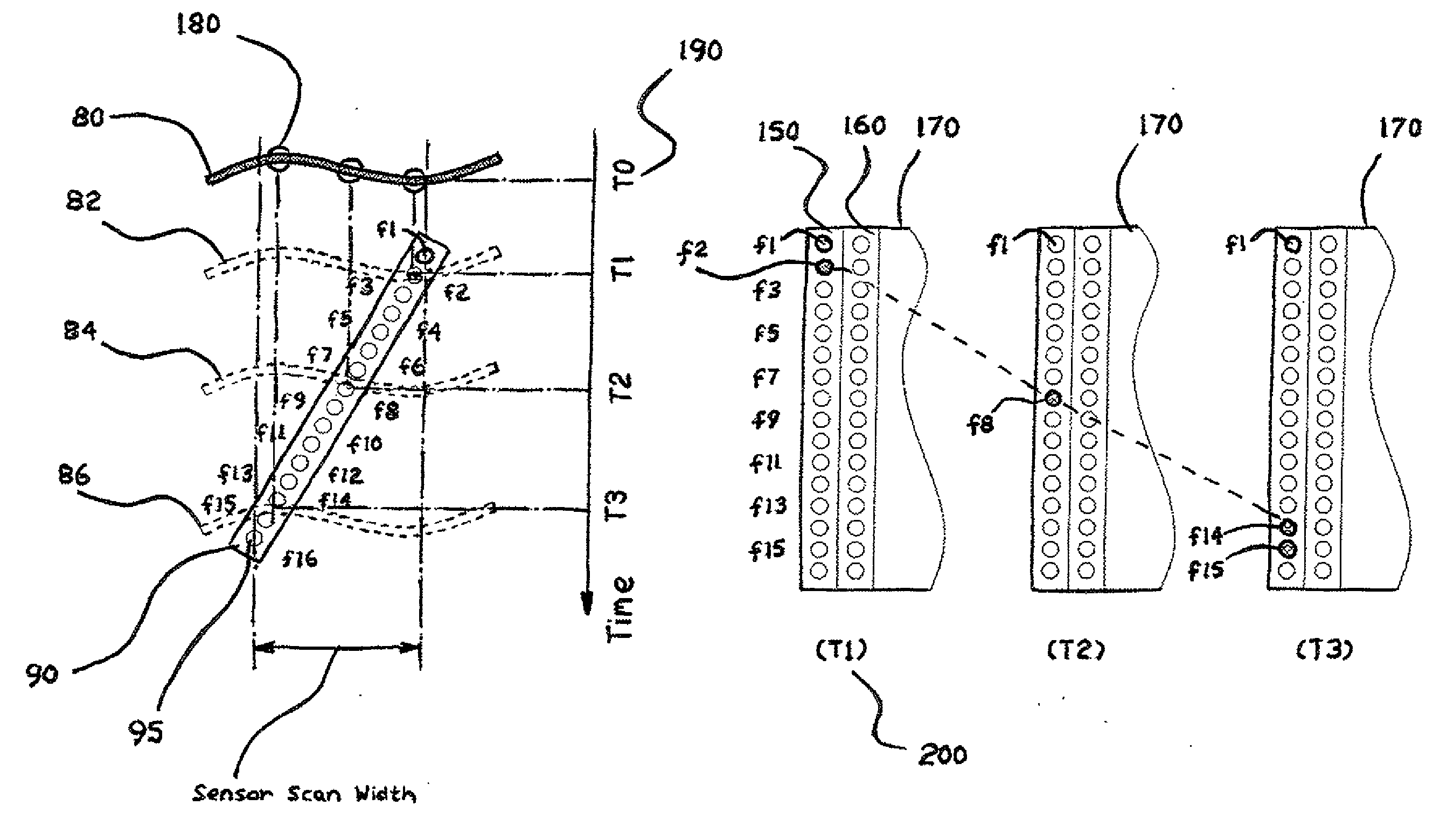
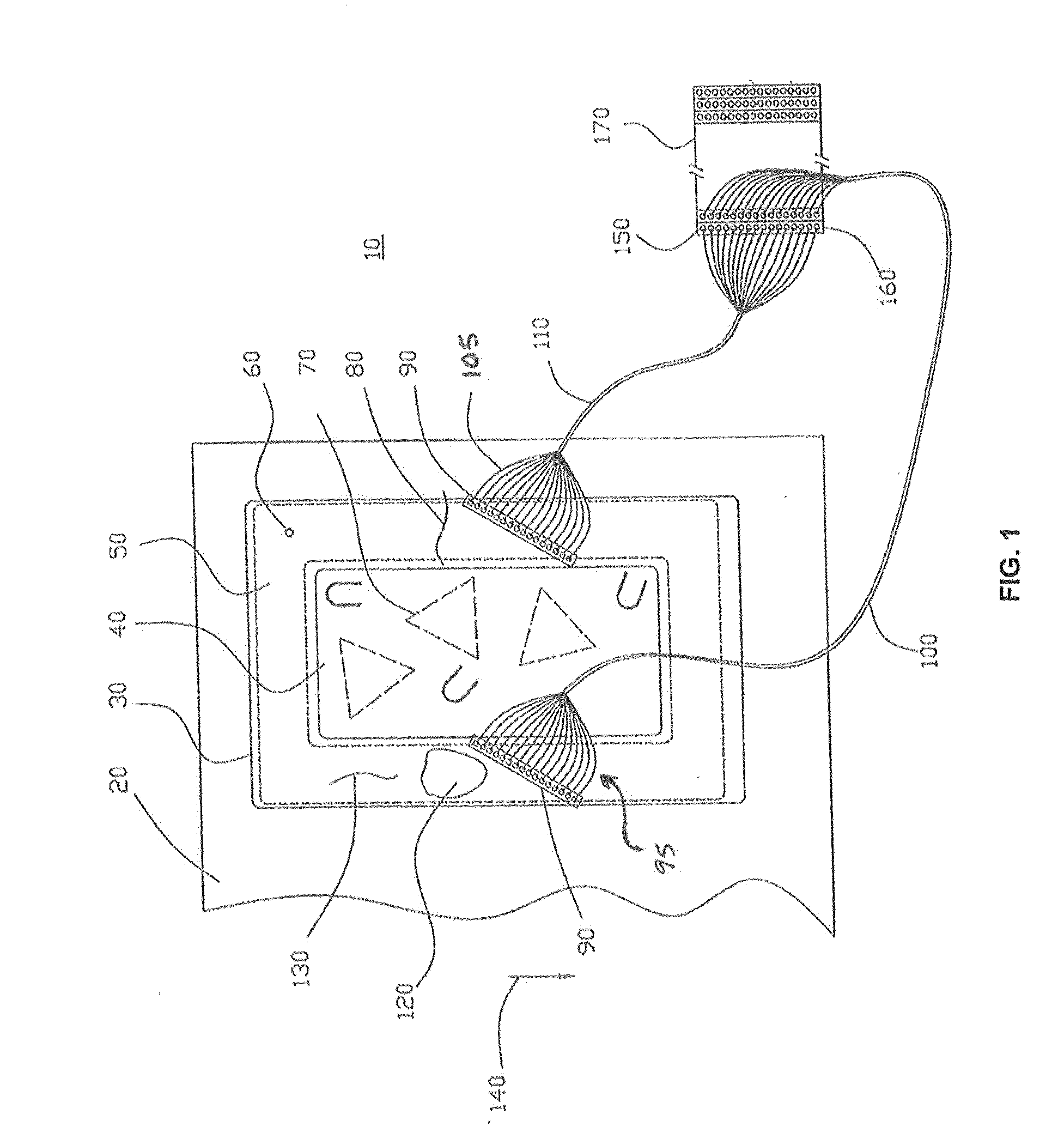
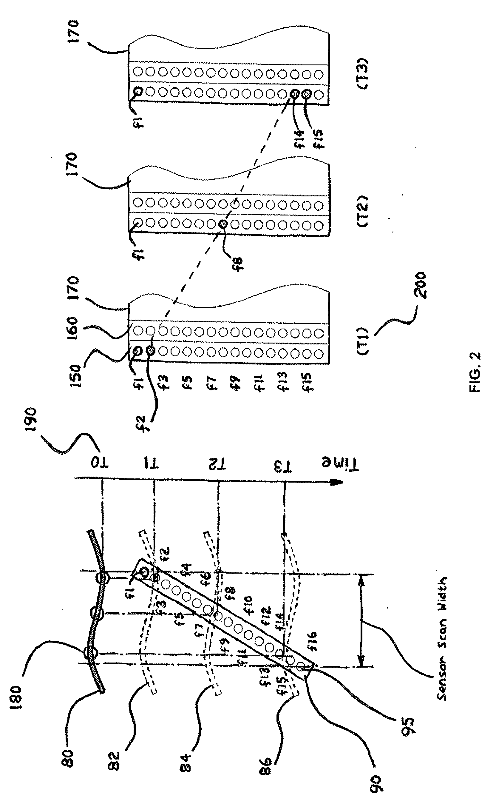
[0018]FIG. 1 is a schematic illustration of the multi-head optical scanner 10 employing fiber optic sensor arrangements 90 (e.g., an array) for transmitting optical energy. Each sensor 95, 105 is comprised of bundle of optical fibers 100, 110 arranged in a linear face 90 oriented towards a scanning area (or areas) of a package 20. As an example, the package 20 illustrated in FIG. 1 includes a sterile area including a sealed pocket 40 defined by a border 30 and includes a sealing area 50. Sterile objects (e.g., surgical tools) 70 are contained within the pocket 40. Input from the sensors 90 can be combined together into 2×D area face 170. In the illustrated embodiment, the multi-head optical scanner is shown with only two stationary sensors 95, 105 that could perform a scan of t...


PUM


Abstract

An inspection station identifies defects such as artifacts (e.g., dust, hair, particles) in the sealing areas of sealed sterile packages. A multi-head optical scanner can include at least two fiber optic sensors each comprised of a bundle of optical fibers arranged into a linear face coupled to an image processing module and oriented towards a scanning area of sealed packages moving through a conveyance system. An image processing module can analyze input from the at least two fiber optic sensor arrangements to identify artifacts in the sealing areas of the sealed packages.

Description

INVENTION PRIORITY[0001]The present invention claims priority of Provisional Patent Application No. 61 / 104,203, filed Oct. 9, 2008, entitled “method and apparatus for detecting defects and embedded objects in sealed sterilized packaging,” which is hereby incorporated by reference.TECHNICAL FIELD OF THE INVENTION[0002]The embodiments of the invention are generally related to the field of automated packaging processes, and in particular, to sterilized packaging. More particularly, the embodiments of the invention are related to methods, systems and apparatuses for detecting defects and embedded object in sealed, sterilized packaging within an automated system and process.BACKGROUND OF THE INVENTION[0003]The present invention relates to the quality control of the sealed sterile packaging process. Various micro objects (e.g., human hair, dust, injection molding debris, etc.) can become embedded between sealing surfaces, which can compromise the sealing of sterile surgical instruments in...

Claims


Application Information

Patent Timeline
IPC IPC(8): H04N7/18G01N21/88
CPCG01N21/9018G01N2201/0833G01N21/95G01N21/94G02B6/06G02B2006/0098G06T7/0008G06T2207/30108
Inventor DJACHIACHVILI, YOURI N.
Owner TEAM TECH
Why Eureka
Try Eureka