Projection display device

Inactive Publication Date: 2010-05-13
PANASONIC CORP
View PDF6 Cites 5 Cited by
  • Summary
  • Abstract
  • Description
  • Claims
  • Application Information

AI Technical Summary

Benefits of technology

[0028]With this configuration, it is possible to reduce a loss of the illumination light caused by the first diaphragm, while securing the light shielding property for

Problems solved by technology

There is a tendency for the illuminant image of the lamp 1 to be brightest in a central region dose to an optical axis and become dark rapidly toward the circumference, so that the brightness is non-uniform.
At either of the times of the ON signal and the OFF signal, the flat light 18 is partially incident on

Method used


Image

  • Projection display device
  • Projection display device
  • Projection display device

Examples


embodiment

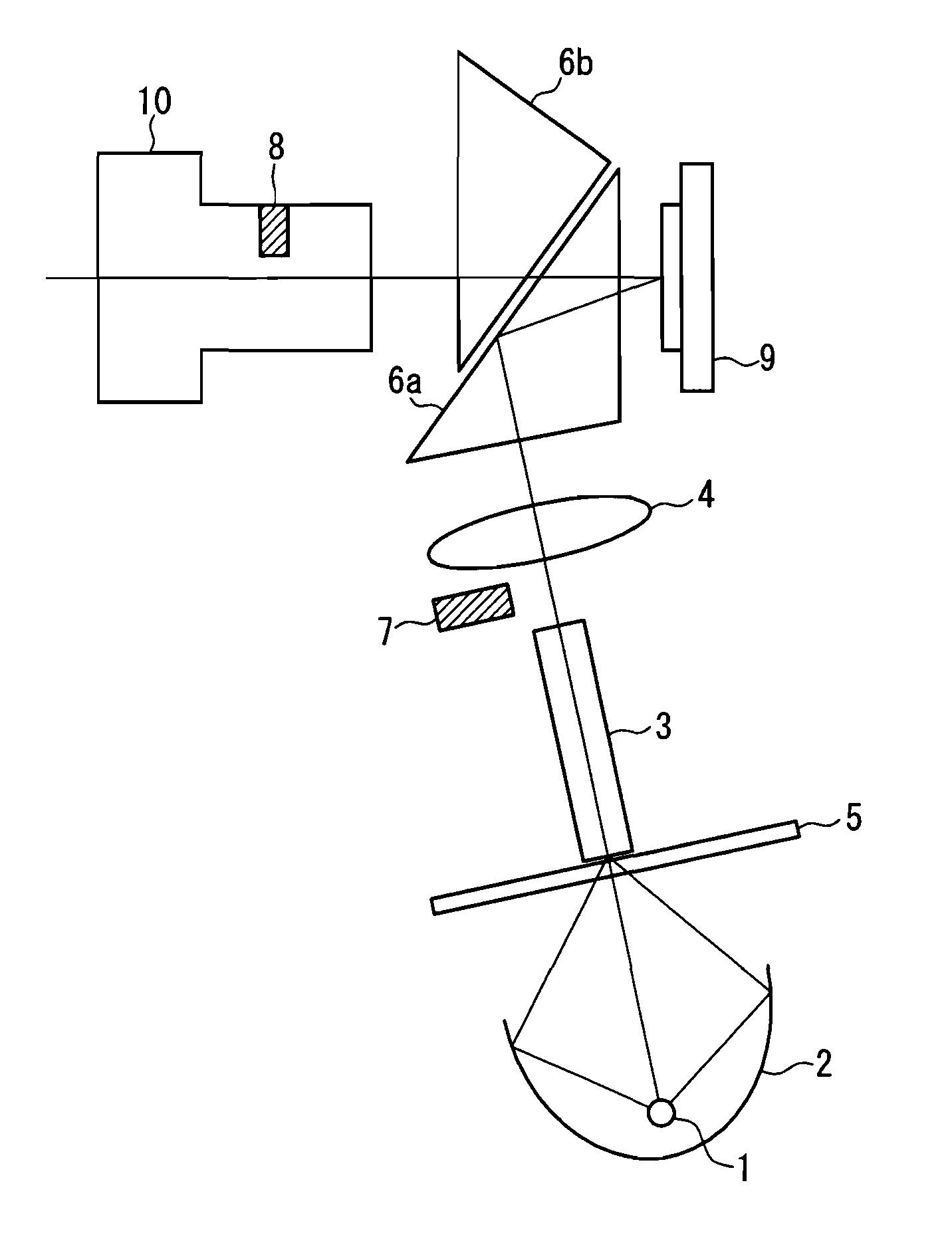
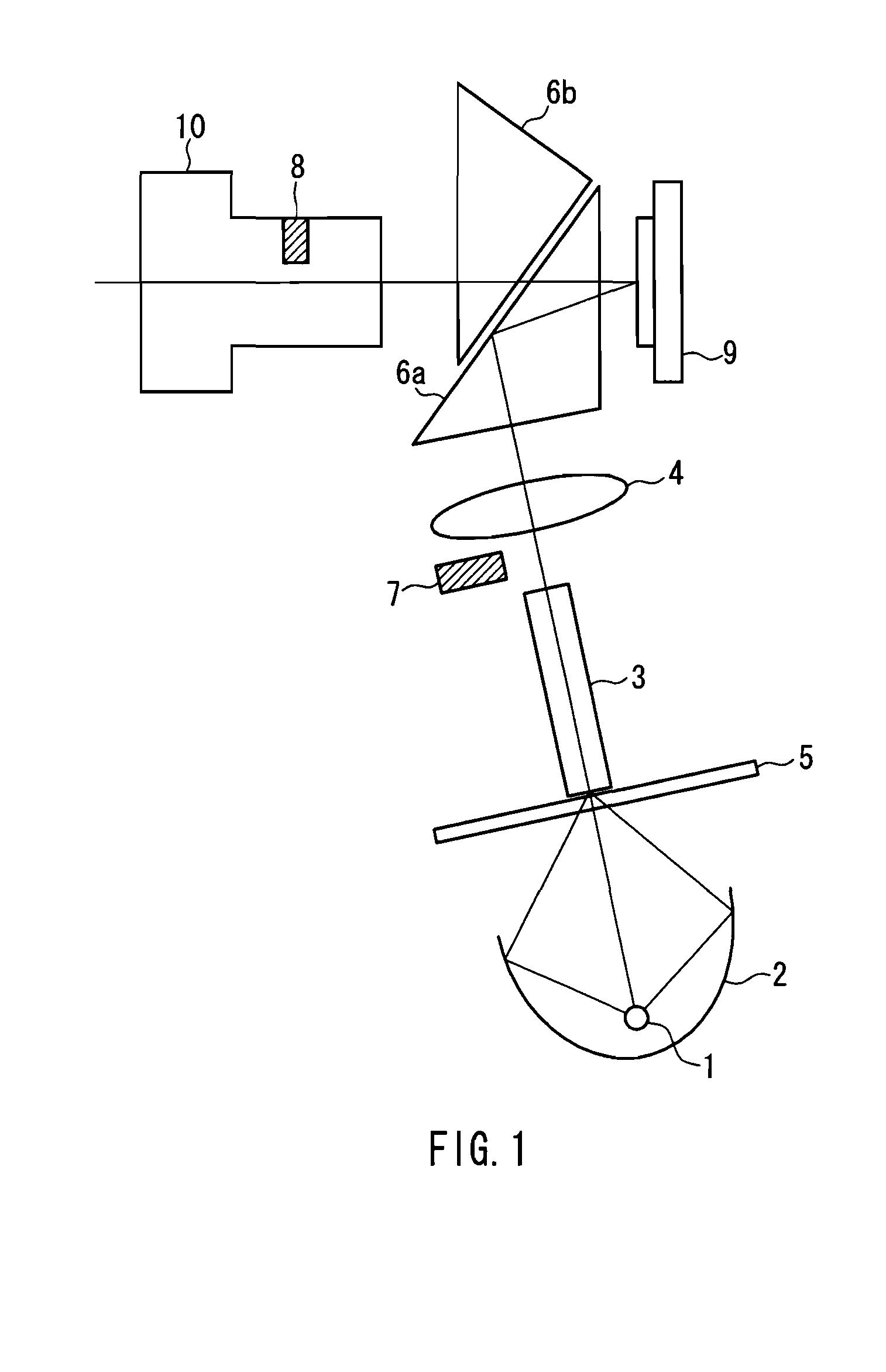
[0072]FIG. 1 is a view showing a configuration of an optical system of a projection display device according to an embodiment of the present invention. In FIG. 1, a lamp 1 as a light source, a concave mirror 2, a rod prism 3, a condenser lens 4, a color wheel 5, a dichroic prism 6, a reflection-type light valve 9, and a projection lens 10 have the same configurations as those in the conventional example shown in FIG. 4.

[0073]In the present embodiment, instead of the diaphragm 11 in the conventional example shown in FIG. 4, a first diaphragm 7 provided at a position of a pupil of an illumination optical system and a second diaphragm 8 provided at a position of a pupil of the projection lens 10 are used in combination so as to function to block flat light. The configurations of the first diaphragm 7 and the second diaphragm 8 will be described later.

[0074]As in the conventional example shown in FIG. 5, the reflection-type light valve 9 has mirror elements 12 formed in a matrix on a pi...


PUM


Abstract

A device includes a light source 1, a reflection-type light valve 9 that controls a traveling direction of exiting light based on an input signal, an illumination optical system 2, 3, 4, 6a that focuses light from the light source on the reflection-type light valve as illumination light, a projection lens 10 that projects exiting light from the reflection-type light valve, a first diaphragm 7 provided at a position of a pupil of the illumination optical system so as to block a part of the light from the light source, and a second diaphragm 8 provided at a position of the pupil of the projection lens so as to block a part of the exiting light from the reflection-type light valve. A part of the illumination light reflected from a surface of the reflection-type light valve to be incident on a pupil of the projection lens as unnecessary light is blocked by a combination of the first diaphragm and the second diaphragm. The light shielding region of the first diaphragm corresponds to a divided region on an outer peripheral side between divided regions obtained by dividing the region of the pupil of the illumination optical system corresponding to the range of the unnecessary light by a line in a chord direction, and a light shielding region of the second diaphragm is shaped and arranged so as to correspond to the divided region on a center side. The unnecessary light incident on the projection lens is blocked efficiently, thereby achieving high brightness performance.

Description

TECHNICAL FIELD[0001]The present invention relates to a projection display device that magnifies and projects an optical image formed on a light valve onto a screen.BACKGROUND ART[0002]A projection display device such as a projector is well known, which forms an optical image based on a video signal on a light valve, and illuminates the optical image with light so as to magnify and project the optical image onto a screen with a projection lens, whereby a large screen video image is obtained.[0003]In such a projection display device, when a reflection-type light valve is used as a light valve, both a high resolution and a high pixel aperture ratio can be achieved, whereby it becomes possible to display a high-brightness projected image with high light utilization efficiency.[0004]FIG. 4 shows a configuration of an optical system in a conventional projection display device using a reflection-type light valve as described above. Such a configuration is disclosed in Patent Document 1, f...

Claims


Application Information

Patent Timeline
IPC IPC(8): H04N5/74G03B21/14G03B21/28
CPCG03B21/20G03B21/008H04N9/3155
Inventor KATO, KENTAROFUSHIMI, YOSHIMASA
Owner PANASONIC CORP
Why Eureka
Try Eureka