Backlight device and liquid crystal display device

a liquid crystal display and backlight technology, applied in static indicating devices, instruments, planar/plate-like light guides, etc., can solve the problems of limit on the widening of the dimming range and the difficulty of widening the dimming range, so as to suppress the decrease in the service life of the light source, improve the contrast ratio, and suppress the increment of the value

Inactive Publication Date: 2010-05-13
SHARP KK
View PDF2 Cites 7 Cited by
  • Summary
  • Abstract
  • Description
  • Claims
  • Application Information

AI Technical Summary

Benefits of technology

[0011]In the present invention, a backlight device is provided with a sub-light source in addition to a main light source, and therefore, can obtain an amount of light that can hardly be obtained by the conventional backlight device that is provided with only a main light source. Besides, in the present invention, this makes it unnecessary to perform current dimming with respect to a fluorescent tube in addition to PWM dimming as in the conventional case, thereby suppressing an increment in a value of current passing through the fluorescent tube (main light source). Therefore, the backlight device according to the present invention is capable of improving a contrast ratio while suppressing a decrease in a service life of a light source.

Problems solved by technology

The current dimming method, in which the dimming is performed by increasing or decreasing current passing through the fluorescent tube, has a difficulty in widening a dimming range.
However, even if the PWM dimming method is adopted, there is a limit on the widening of the dimming range.

Method used


Image

  • Backlight device and liquid crystal display device
  • Backlight device and liquid crystal display device
  • Backlight device and liquid crystal display device

Examples


embodiment 1

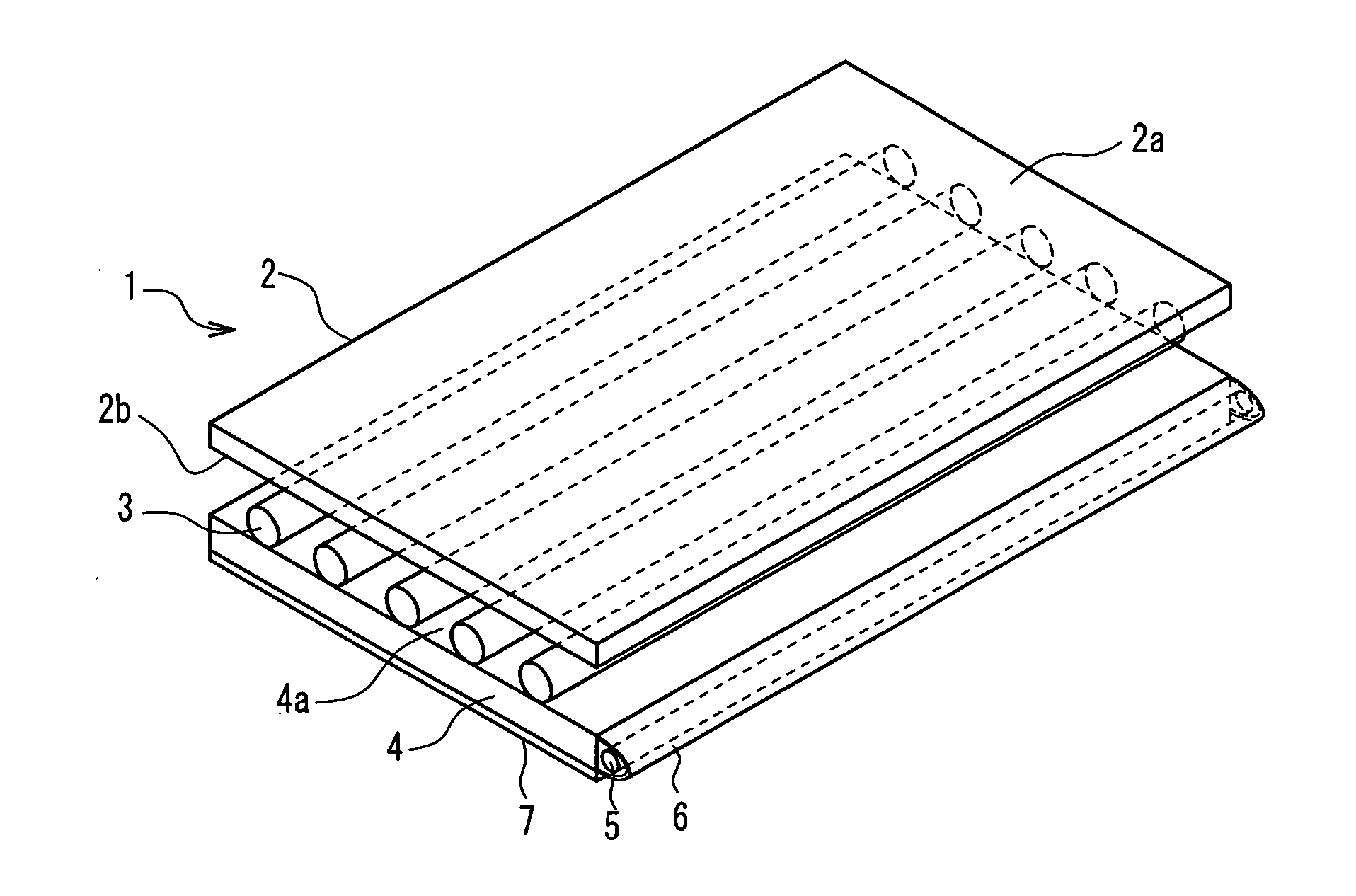
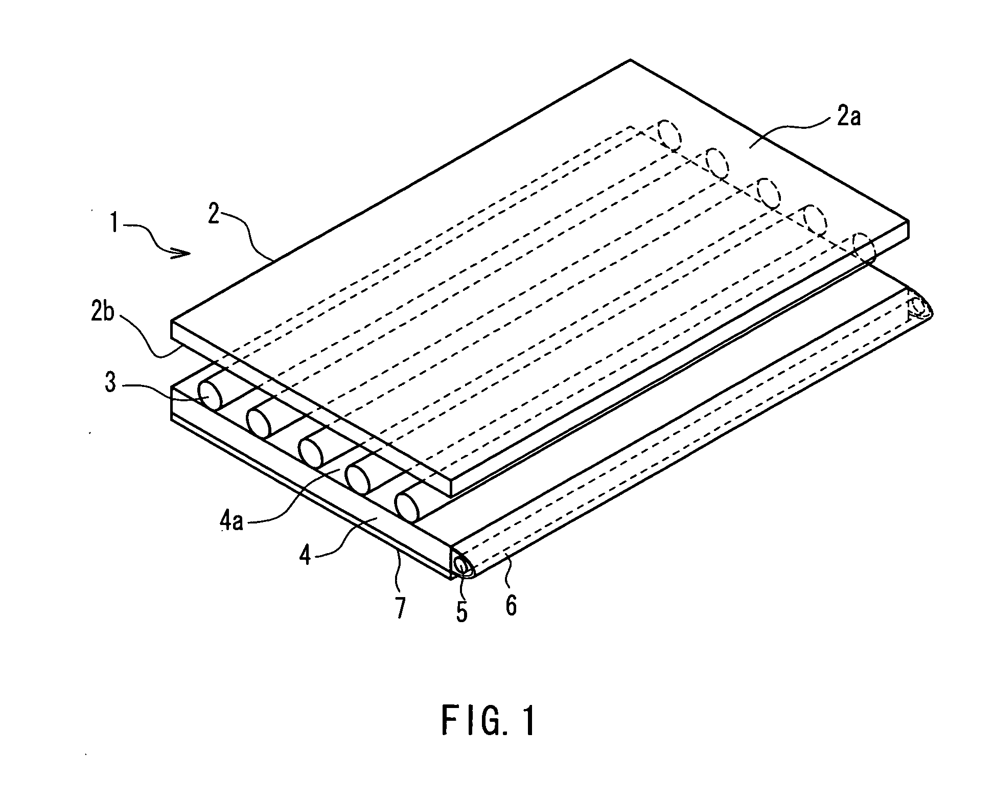
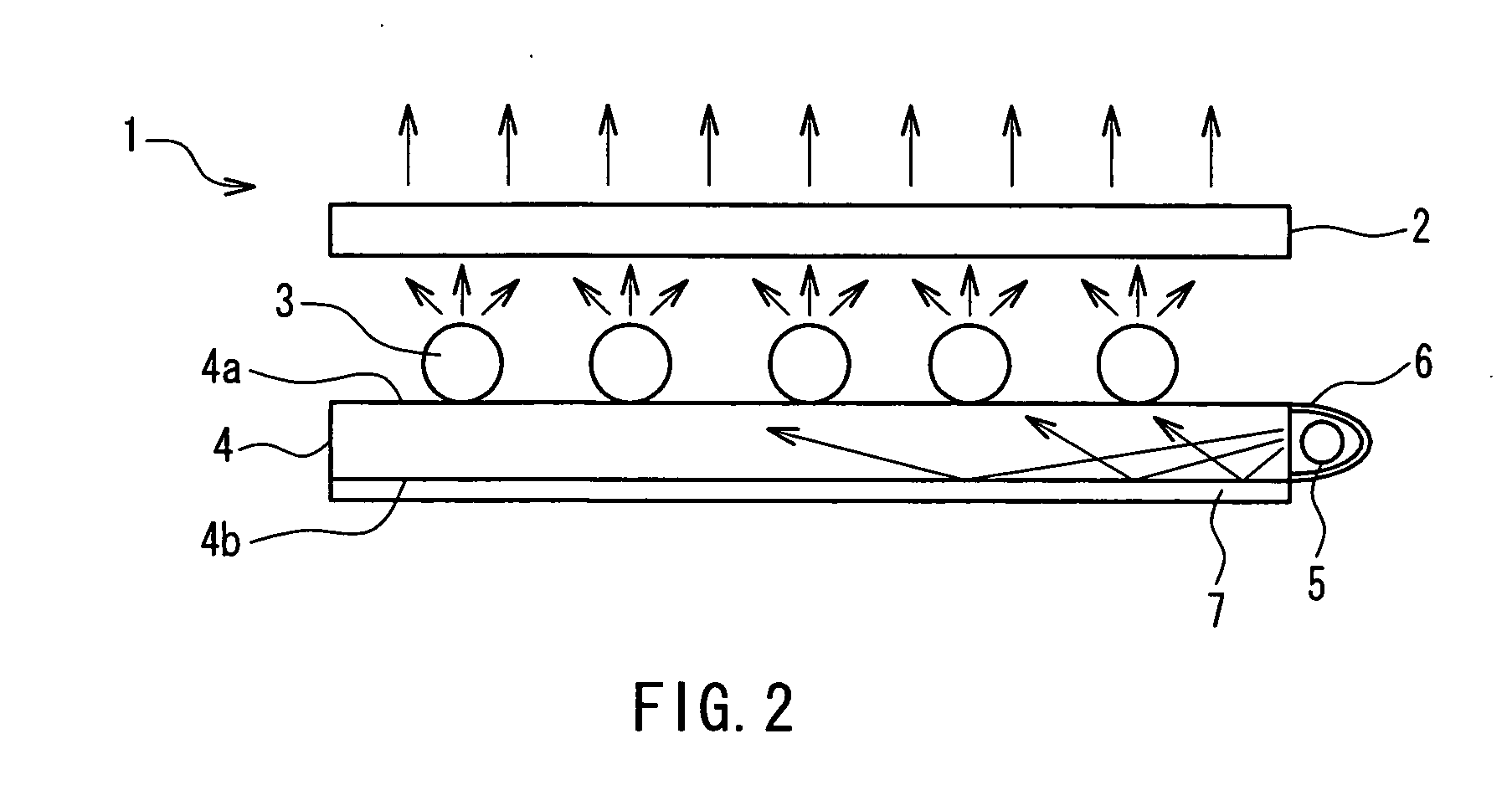
[0027]Hereinafter, a backlight device and a liquid crystal display device in Embodiment 1 of the present invention will be described with reference to FIGS. 1 to 6. First, a schematic configuration of an optical portion of the backlight device in the present Embodiment 1 will be described with reference to FIGS. 1 and 2. FIG. 1 is a perspective view three-dimensionally showing a schematic configuration of an optical portion of a backlight device according to Embodiment 1 of the present invention. FIG. 2 is a side view of the optical portion of the backlight device shown in FIG. 1.

[0028]As shown in FIGS. 1 and 2, a backlight device 1 in the present Embodiment 1 includes the following as an optical portion: an optical layer 2, a main light source 3, a light guide plate 4, and a sub-light source 5. Although it is not shown in FIG. 1 or 2, the backlight device 1 further includes a driving portion (see FIG. 3) for driving the main light source 3 and the sub-light source 5.

[0029]The optic...

embodiment 2

[0051]Next, a backlight device and a liquid crystal display device in Embodiment 2 of the present invention will be described with reference to FIGS. 7 to 9. FIG. 7 is a block diagram showing configurations of a backlight device and a liquid crystal display device according to Embodiment 2 of the present invention. FIG. 8 is a block diagram showing a specific configuration of a driving portion constituting the backlight device shown in FIG. 7. FIG. 9 is a circuit diagram exclusively showing a portion for driving the sub-light source in the driving portion shown in FIG. 7.

[0052]In the present Embodiment 2, a backlight device 41 includes a plurality of light-emitting diodes as a sub-light source 42, which differs from the backlight device 1 in Embodiment 1. Further, since the sub-light source 42 is formed of light-emitting diodes, a configuration of a driving portion 43 also differs from that of the driving portion 8 in Embodiment 1.

[0053]Except the aforementioned differences, the bac...


PUM

PropertyMeasurementUnit
widthaaaaaaaaaa
currentaaaaaaaaaa
brightnessaaaaaaaaaa

Abstract

In one embodiment of the present invention, a backlight device is disclosed wherein a contrast ratio is improved with a decrease in light source service life being suppressed, and a liquid crystal display device using such backlight device. The backlight device is provided with an, optical layer whose main surface is a light outgoing surface; a main light source that is arranged at a position facing a main surface of the optical layer and emits light toward the optical layer; a light guide plate that is arranged on a main surface side, so as to be parallel to the main surface, and has a main surface on an optical layer side as a light outgoing surface; a sub-light source that is arranged at a position facing a side surface of the light guide plate and emits light toward the side surface; and a driving portion for driving the main light source and the sub-light source. The main light source is provided with a plurality of fluorescent tubes arranged parallel to the optical layer. The driving portion outputs drive pulses to the plurality of the fluorescent tubes, respectively, and adjusts the light amounts of the plurality of the fluorescent tubes by modulating the pulse widths of the drive pulses (PWM dimming method).

Description

TECHNICAL FIELD[0001]The present invention relates to a backlight device, and to a liquid crystal display device provided with the backlight device.BACKGROUND ART[0002]In general, a liquid crystal display device, except for a reflection type that forms images by reflecting external light, is provided with a backlight device. Some of such backlight devices utilize fluorescent tubes or light-emitting diodes as light sources. The fluorescent tube is mostly used as a light source for the backlight device, with a light amount and a service life being taken into consideration.[0003]Further, in the liquid crystal display device, dimming of the backlight device is performed automatically or manually in accordance with the ambient light intensity, the contrast of a display image, and the like. As the dimming method adopted when a fluorescent tube is used as a light source of the backlight device, the current dimming method and the PWM (Pulse Width Modulation) dimming method are known.[0004]T...

Claims


Application Information

Patent Timeline
Patent Type & Authority Applications(United States)
IPC IPC(8): G02F1/1335H05B41/26
CPCG02B6/005G02B6/0071G02F1/133604G02F1/133615H05B41/3927G09G3/3611G09G2320/064G09G2320/066H05B35/00G09G3/3406
Inventor MURAO, MASAYUKI
Owner SHARP KK
Why Eureka
Try Eureka