Concept for Realistic Simulation of a Frequency Spectrum

Active Publication Date: 2010-05-13
INNOVATIONSZENTRUM FUER TELEKOMMUNIKATIONSTECHNIK GMBH IZT
View PDF6 Cites 33 Cited by
  • Summary
  • Abstract
  • Description
  • Claims
  • Application Information

AI Technical Summary

Benefits of technology

[0015]For simulating a frequency spectrum occupancy as realistically as possible, it is mainly necessitated to be able to simulate as many relatively narrow-band transmitters or emitters, respectively, as possible. The inventive concept has the advantage that with a high number of emitters, in particular narrow-band emitters, the resource requirements for simulating the signal composed of a plurality of individual signals are low. This is in particularly due to the fact that for transforming the individual signals to the frequency domain, a FFT with comparatively short length is used, whereas for calculating the combined output signal, an IFFT with greater length is used. Due to the short input-side FFT length, a high number of emitters can be simulated with little effort.
[0016]It is a further advantage of embodiments of the

Problems solved by technology

However, the disadvantage of this method is that respective memory requirements in an AWG are comparatively high, since the emitter signals have to be stored in a transmittable signal bandwidth.
Further, the time needed for calculating the data is long and is normally by orders of mag

Method used


Image

  • Concept for Realistic Simulation of a Frequency Spectrum
  • Concept for Realistic Simulation of a Frequency Spectrum
  • Concept for Realistic Simulation of a Frequency Spectrum

Examples


Example

[0026]With regard to the following description, it should be noted that similar or equal functional elements have the same reference numbers in the different embodiments and thus the description of these functional elements can be interchanged in the different embodiments presented below.

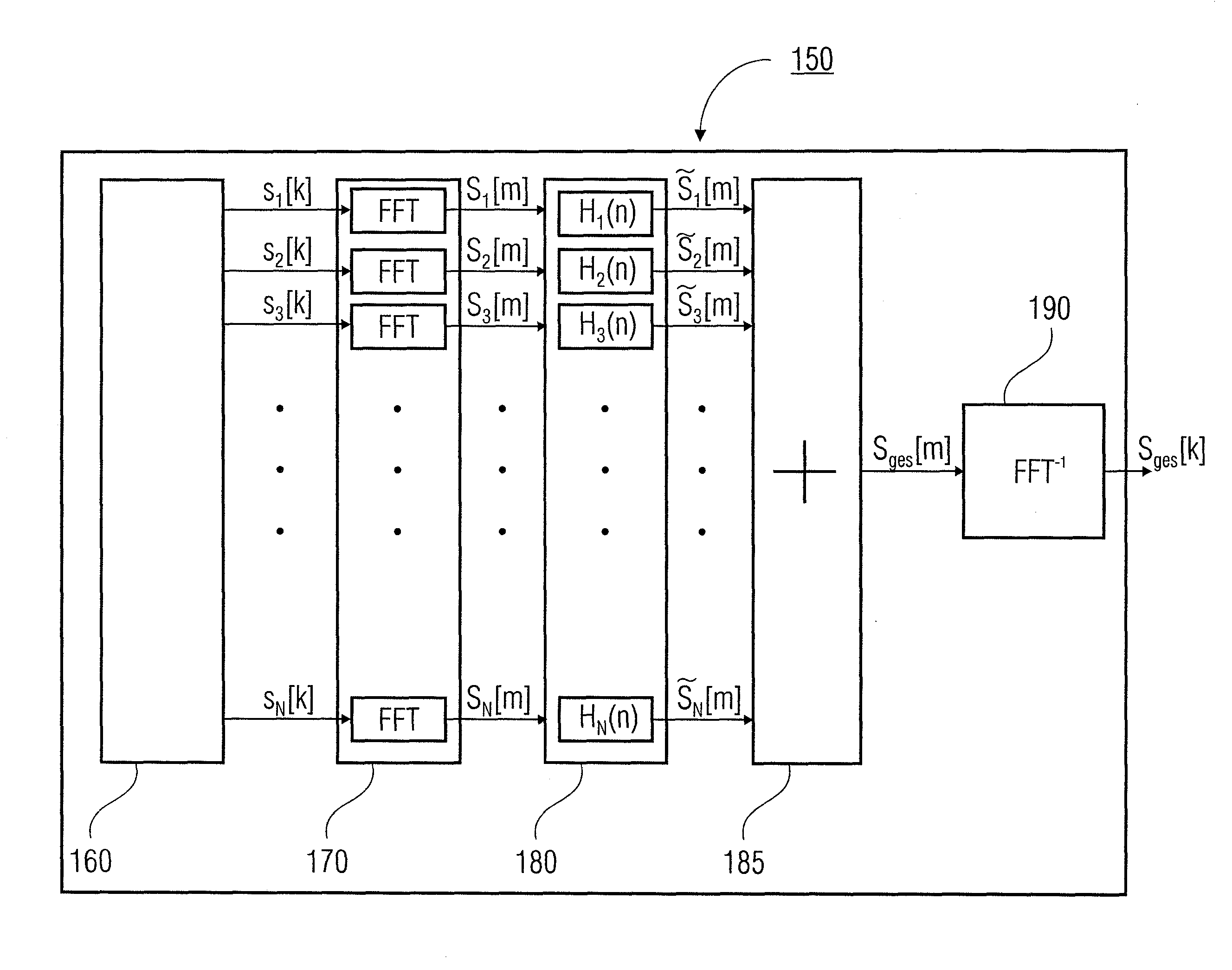
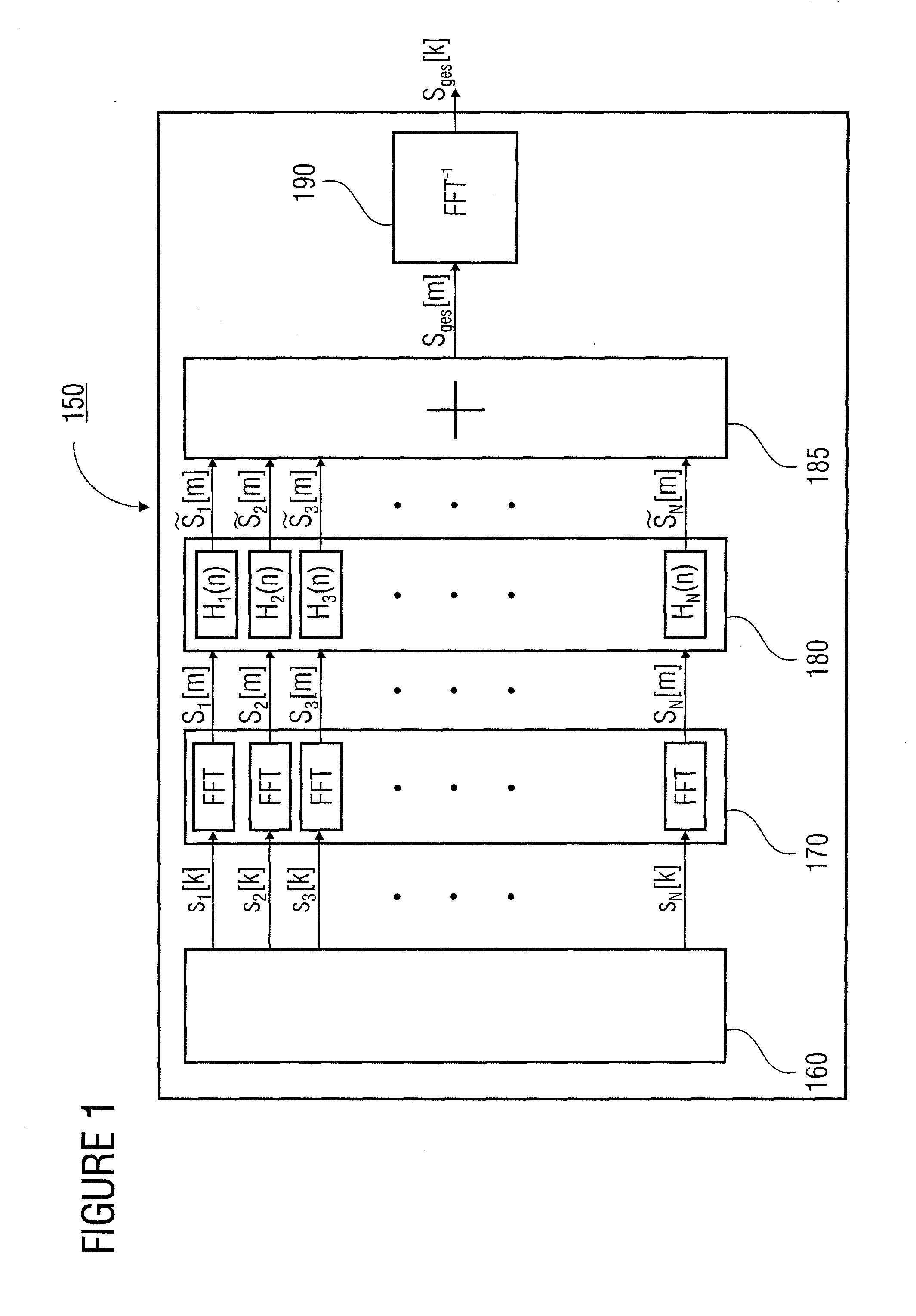
[0027]FIG. 1 shows a block diagram of an apparatus for simulating a signal composed of a plurality of individual signals from respective signal locations at a simulation location according to an embodiment of the present invention.

[0028]The apparatus 150 comprises a means for providing the plurality of time-discrete baseband individual signals s1[k] to sN[k] in the time domain, a means 170 for transforming the time-discrete individual signals s1[k] to sN[k] to a frequency-discrete baseband frequency domain, a means 180 for processing the individual signals s1[m] to sN[m] transformed to the baseband frequency domain, a means 185 for combining the processed individual signals {tilde over (S)}1[m] to {...


PUM


Abstract

An apparatus for simulating a signal composed of a plurality of individual signals from respective signal locations at a simulation location, having a provider for providing the plurality of individual signals in the time domain, a transformer for transforming the individual signals to the frequency domain, a processor for processing the individual signals transformed to the frequency domain each depending on a signal channel existing between the simulation location and the respective signal location, a combiner for combining the processed individual signals transformed to the frequency domain to a combined signal, and a transformer for transforming the combined signal to the time domain for generating the simulated combined signal at the simulation location.

Description

CROSS-REFERENCE TO RELATED APPLICATIONS[0001]This application is a U.S. national entry of PCT Patent Application Serial No. PCT / EP2007 / 007593 filed 30 Aug. 2007, and claims priority to German Patent Application No. 102006043411.0-35 filed 15 Sep. 2006, each of which is incorporated herein by reference.BACKGROUND OF THE INVENTION[0002]The present invention relates to an apparatus and a method for simulating a signal composed of plurality of individual signals, as it can be used in particular for realistic simulation of a frequency spectrum.[0003]Methods for localization of transmitters or emitters of radio waves, respectively, such as radio direction finding, are methods where an individual position of a radio direction finder or a position and / or direction of a transmitter or emitter, respectively, can be determined, for example by direction finding or timing of a radio signal. Frequently, a relative velocity between transmitter and receiver can also be determined. Radio direction f...

Claims


Application Information

Patent Timeline
IPC IPC(8): G06F17/14G06F17/17G06F5/01
CPCG01S3/026H04L27/2637H04L27/26
Inventor GRUENER, UWEKLOSE, ANREASPERTHOLD, RAINERZIMMERMANN, ROLAND
Owner INNOVATIONSZENTRUM FUER TELEKOMMUNIKATIONSTECHNIK GMBH IZT
Why Eureka
Try Eureka