Automatically switching console connection
- Summary
- Abstract
- Description
- Claims
- Application Information
AI Technical Summary
Problems solved by technology
Method used
Image

Examples
first embodiment
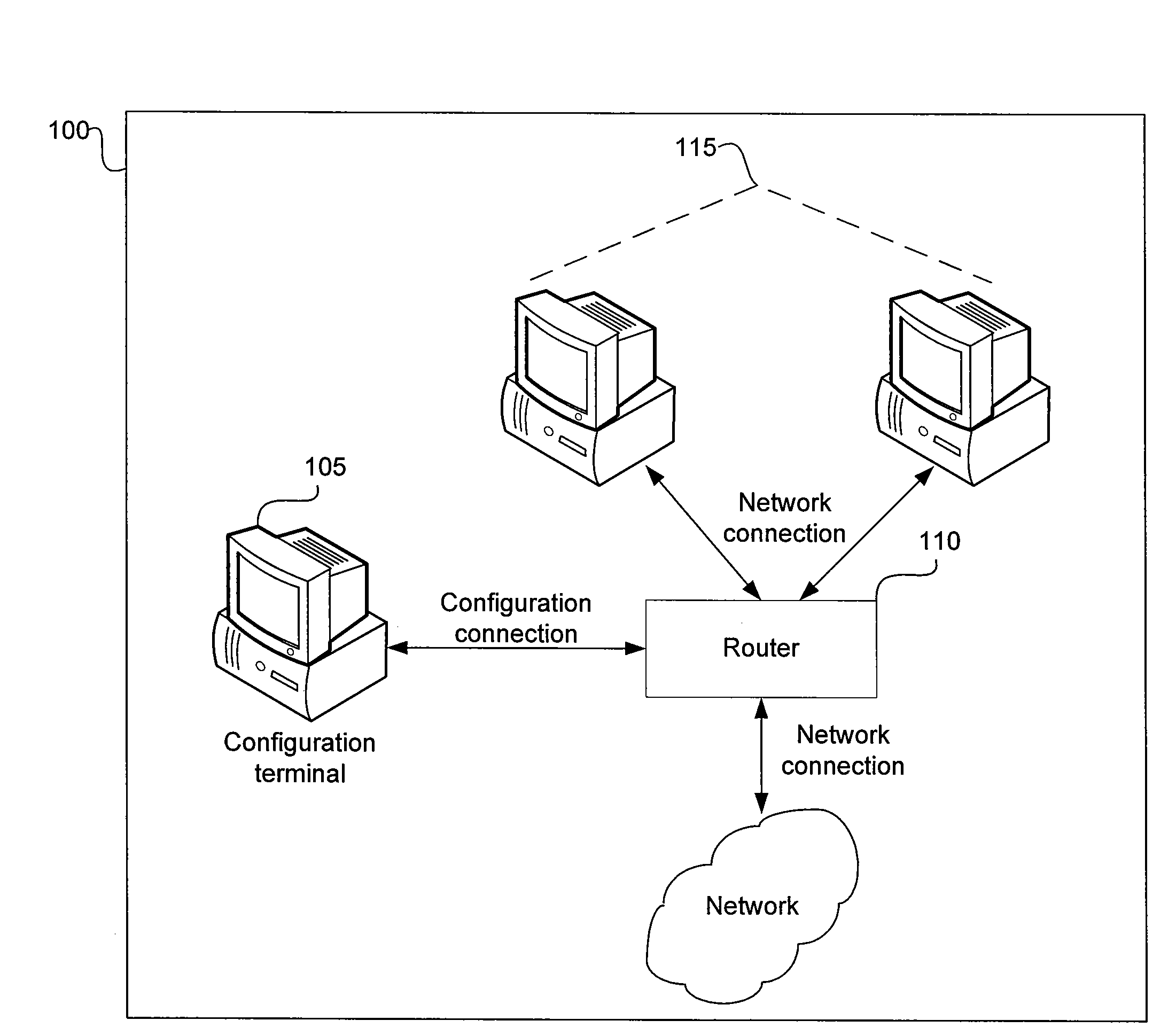
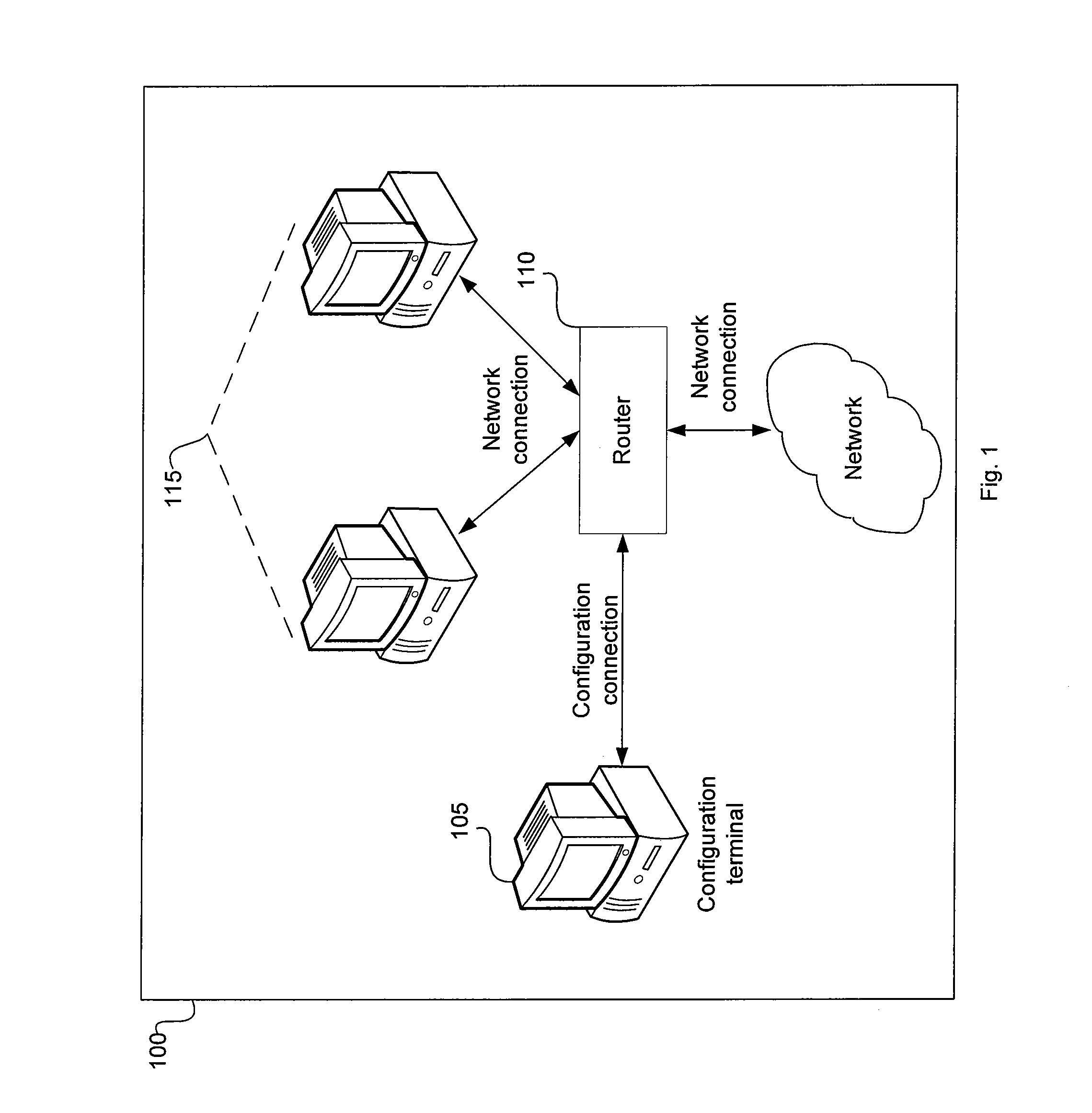
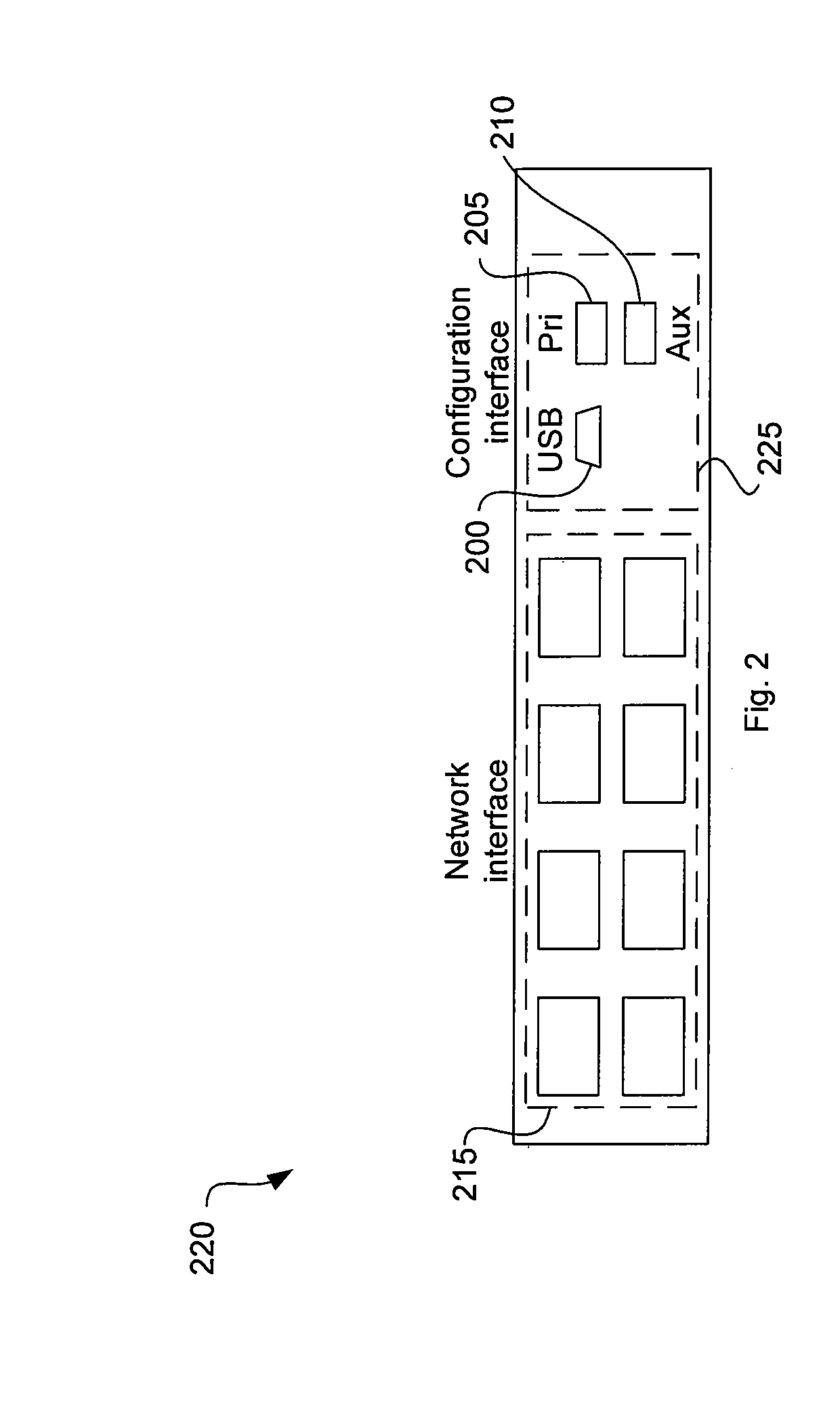
[0025]FIG. 3 is a schematic representation of network device interface circuitry 300. The network device interface circuitry 300 includes a CPU 305, a first universal-asynchronous-receiver-transmitter (UART) 335, a second universal-asynchronous-receiver-transmitter (UART) 340, a multiplexer 310, a USB-to-serial converter 315, a primary serial input conditioning circuit 320, an auxiliary serial input conditioning circuit 325, a memory 345, a USB interface 350, a primary serial interface 355, and an auxiliary serial interface 360. Additional, different, or fewer components may be provided, such as not providing the auxiliary path. The network device interface circuitry 300 may reside in the network device 110 of FIG. 1. The USB interface 350, primary serial interface 355, and auxiliary serial interface 360 may correspond to the USB interface 200, primary serial interface 205, and auxiliary serial interface 210 of FIG. 2.
[0026]The primary serial input conditioning circuit 320 and auxil...
second embodiment
[0034]FIG. 4 is a schematic representation of network device interface circuitry 400. The network device interface circuitry 400 includes a CPU 405, a first UART 435, a second UART 440, a multiplexer 410, a USB-to-serial converter 415, a primary serial input conditioning circuit 420, an auxiliary serial input conditioning circuit 425, a memory 445, a USB interface 450, a primary serial interface 455, and an auxiliary serial interface 460. Additional, different, or fewer components may be provided. The network device interface circuitry 400 may reside in the network device 110 of FIG. 1.
[0035]The second embodiment of the network device interface circuitry 400 may operate similarly to the first embodiment of the network device interface circuitry 300 of FIG. 3. In addition to the functionality described above, in the second embodiment, a detection signal 430 may be communicated from the USB-to-serial converter 415 to the CPU 405 and the CPU 405 may communicate a selection signal 465 t...
fourth embodiment
[0037]FIG. 5 is a schematic representation of network device interface circuitry 500. The network device circuitry 500 includes a processor 505, a communication port 525, a multiplexer 510, a converter circuit 515, a first configuration interface 535, a second configuration interface 530. The network device circuitry 500 may reside in the network device 110 of FIG. 1. The first configuration interface 535 and second configuration interface 530 may correspond to the primary serial interface 205 and USB interface 200, respectively of, FIG. 2.
[0038]The processor 505 may include logic, memory, circuitry, software, or firmware that enables performing various operations associated with the network device. For example, the processor 505 may be adapted to direct data from one network interface of the network device to another network interface and also to generate a configuration web page in response to a web page request from a computer connected to one of the network interfaces. The proce...
PUM
 Abstract
Description
Claims
Application Information
 - R&D Engineer
- R&D Manager
- IP Professional
- Industry Leading Data Capabilities
- Powerful AI technology
- Patent DNA Extraction
Browse by: Latest US Patents, China's latest patents, Technical Efficacy Thesaurus, Application Domain, Technology Topic.
© 2024 PatSnap. All rights reserved.Legal|Privacy policy|Modern Slavery Act Transparency Statement|Sitemap