Apparatus for wireless power transmission using high Q low frequency near magnetic field resonator

Inactive Publication Date: 2010-05-20
SAMSUNG ELECTRONICS CO LTD
10 Cites 192 Cited by

AI-Extracted Technical Summary

Problems solved by technology

However, since this technology uses a near-field, low frequencies have to be used to transmit power over a short distance, which leads to an inevitable increase in the size of a resonator.
However, due to a need for use of low frequencies in order to effic...

Benefits of technology

[0014]In the resonance circuit to implement the characteristics of the ENG metamaterial, a Q value is increased by forming at least one via in a substrate or the shunt inductor is formed by forming a slot in a substra...

Abstract

An apparatus for wireless power transmission is disclosed. According to an exemplary aspect, the wireless power transmission apparatus includes a high Q low frequency near magnetic field resonator having characteristics of a metamaterial. Accordingly, manufacturing of a compact power supply capable of wirelessly supplying power to mobile communication terminals or multimedia terminals is possible. By using a zeroth-order resonator with a DNG or ENG structure, a small-sized power supply with a simple configuration may be manufactured.

Application Domain

Impedence networksLoop antennas +1

Technology Topic

Image

  • Apparatus for wireless power transmission using high Q low frequency near magnetic field resonator
  • Apparatus for wireless power transmission using high Q low frequency near magnetic field resonator
  • Apparatus for wireless power transmission using high Q low frequency near magnetic field resonator

Examples

  • Experimental program(1)

Example

[0023]Reference will now be made in detail to embodiments, examples of which are illustrated in the accompanying drawings, wherein like reference numerals refer to like elements throughout. In this regard, embodiments of the present invention may be embodied in many different forms and should not be construed as being limited to embodiments set forth herein. Accordingly, embodiments are merely described below, by referring to the figures, to explain aspects of the present invention.
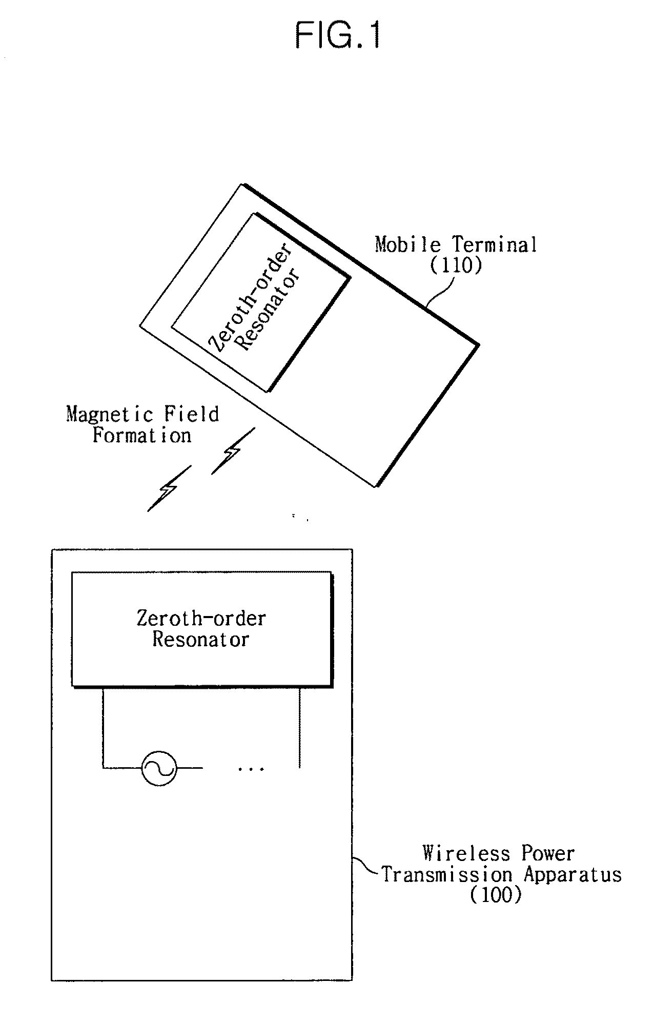
[0024]FIG. 1 is a view for explaining the concept of a wireless power transmission apparatus 100 using resonance coupling of a zeroth-order resonator.
[0025]The wireless power transmission apparatus 100 includes a zeroth-order resonator. In FIG. 1, a mobile terminal 110 also includes a zeroth-order resonator and receives power through a magnetic field created by resonance coupling. The received power is stored in the rechargeable battery of the mobile terminal 110.
[0026]Studies on zeroth-order resonators have been mainly made in association with applications for antennas using far-fields. However, zeroth-order resonators, are more suitable to applications using near fields as a zeroth-order resonator has a planer structure, high Q (quality factor) value and low transmission efficiency. However, as there are few appropriate applications using near-fields, studies on the application of antennas using far-fields have been actively made to date.
[0027]A zeroth-order resonator may be applied as a near-field resonator in which the effect of a magnetic field is more dominant than those of an electric field. A high Q value near magnetic field resonator according to an exemplary embodiment utilizes this property.
[0028]Wireless power transmission using resonance coupling uses a near field. The higher the Q value, the higher the energy transmission efficiency, as seen in Equation 1 below.
η(transmission efficiency)=K/Γ Equation 1
[0029]Here, K represents intensity of resonance coupling, and Γ represents 1/Q.
[0030]As understood by Equation 1, if a zeroth-order resonator which has a relatively high Q value and whose resonance frequency is independent from an operating frequency is used, a small-sized resonator which has high power transmission efficiency may be implemented.
[0031]Also, since the zeroth-order resonator has a field which is in the form of a magnetic dipole at a resonance frequency, the effects of a magnetic field are more dominant than those of the electrical field in a near field. Accordingly, power transmission through magnetic field coupling that is harmless to humans is possible.
[0032]FIGS. 2A and 2B are circuit diagrams of circuits to implement characteristics of a metamaterial using a transmission line.
[0033]In more detail, FIGS. 2A and 2B show circuits that have double-negative (DNG) characteristics or epsilon-negative (ENG) characteristics using a transmission line (TL). Metamaterials are classified according to the real/imaginary nature of values regarding permittivity and magnetic permeability, into DNG whose permittivity and magnetic permeability are all imaginary values, ENG whose magnetic permeability is a positive value and whose permittivity is an imaginary value, and mu-negative (MNG) whose permittivity is a positive value and whose magnetic permeability is an imaginary value.
[0034]Referring to FIG. 2A, a shunt capacitor CR 210 and a series inductor LR 220 are devices on a right handed transmission line, and by adding a series capacitor CL 230 and a shunt inductor LL 240, a transmission line having DNG characteristics may be constructed.
[0035]Also, referring to FIG. 2B, by adding only the shunt inductor LL 240 to the shunt capacitor CR 210 and series inductor LR 220, a transmission line having ENG characteristics may be constructed.
[0036]FIG. 3 is a graph showing dispersion curves of an ENG transmission line and a DNG transmission line.
[0037]Referring to FIG. 3, both the DNG and ENG transmission lines have a resonance mode at a zeroth-order, that is, when n=0. Also, FIG. 3 shows that an ENG transmission line resonator resonates at a lower frequency than a DNG transmission line resonator does when zeroth-order resonance occurs. Consequently, the structure of the ENG transmission line has the advantage of having a resonator configuration with a smaller size than that of the DNG transmission line structure.
[0038]FIG. 4 illustrates the distribution of an electric field 410 and a magnetic field 420 in a zeroth-order resonance mode.
[0039]Referring to FIG. 4, in the zeroth-order resonance mode, the electric field 410 exists only between a substrate and a top plate, and the magnetic field 420 surrounds a resonator as if it is a magnetic dipole. Since the resonator uses a magnetic field, it is preferable that a magnetic field extends outside the substrate while an electric field that is harmful to humans is confined within the substrate, and FIG. 4 shows that the electric field 420 is confined within the substrate.
[0040]FIGS. 5A and 5B are diagrams illustrating a resonator with an ENG structure according to an exemplary embodiment.
[0041]A structure illustrated in FIG. 5A corresponds to the circuit illustrated in FIG. 2B. That is, the structure illustrated in FIG. 5A is a circuit that does not have a series capacitor which the DNG structure requires. Also, in order to configure a high Q resonator, one or more vias 511, 512, and 513 functioning as a shunt inductor L may be added. The Q value of a zeroth-order ENG or DNG resonator may be calculated according to Equation 2, below.
Q=R/(ω0LL)  Equation 2
[0042]Here, ω0 represents a resonance frequency (Radians).
[0043]The Q value is a ratio of energy accumulated in reactive elements, such as capacitors or inductors, to a total energy loss. An ideal resonance circuit is composed of inductors and capacitors, and accumulates energy by transferring current from one element to another.
[0044]As seen in Equation 2, in order to increase the Q value, the inductance of the shunt inductor LL has to be decreased. For this, the current embodiment may use one or more vias. For example, as shown in FIG. 5A, by using three vias 511, 512, and 513, the Q value becomes three time greater than when one via is used. The number of vias is not limited.
[0045]Meanwhile, as illustrated in FIG. 5B, a slot 520 for lengthening a path of current flow may be formed in a substrate 510 so that the slot 520 functions as a shunt inductor LL. In this case, the length, shape, etc., of the slot 520 may vary depending on a demanded Q value, and the shape of the substrate 510 also is not limited to the embodiment shown herein. Also, if the substrate 510 is made of a ferrite material, the electric field is more confined within the substrate 510 and the strength of the magnetic field is increased due to the characteristics of ferrite materials.
[0046]FIG. 6 is a circuit diagram illustrating a circuit of an ENG high Q zeroth-order resonator according to an exemplary embodiment.
[0047]Referring to FIG. 6, parallel-connecting three shunt inductors (LL) 611, 612, and 613 is a circuit of parallel-connecting an inductor (LT) 620 whose inductance is equal to total inductance of the parallel-connecting three shunt inductors (LL) 611, 612, and 613. Therefore, the value of LT is ⅓LL.
[0048]According to an exemplary embodiment, a small-sized power supply which can supply power wirelessly to mobile communication terminals, multimedia terminals, or the like, may be manufactured. Also, a zeroth-order resonator with a DNG or ENG structure which is used to manufacture such a small-sized power supply is compact and has a simple configuration.
[0049]In addition, since a high Q value is obtained by using one or more vias, wireless power transmission using near-field resonance coupling is possible.
[0050]Also, since a zeroth-order resonance mode is used, the effects of a magnetic field become more dominant than those of an electric field in a near-field, which minimizes harmful effects to humans when wireless power transmission occurs.
[0051]Furthermore, by adopting a metamaterial structure, a resonance frequency of the resonator is not proportional to an operating frequency, and accordingly, manufacturing of a compact low-frequency resonator which is significantly smaller than existing loop resonators is possible.
[0052]While aspects of the present invention has been particularly shown and described with reference to differing embodiments thereof, it should be understood that these exemplary embodiments should be considered in a descriptive sense only and not for purposes of limitation. Descriptions of features or aspects within each embodiment should typically be considered as available for other similar features or aspects in the remaining embodiments.
[0053]Thus, although a few embodiments have been shown and described, with additional embodiments being equally available, it would be appreciated by those skilled in the art that changes may be made in these embodiments without departing from the principles and spirit of the invention, the scope of which is defined in the claims and their equivalents.

PUM

no PUM

Description & Claims & Application Information

We can also present the details of the Description, Claims and Application information to help users get a comprehensive understanding of the technical details of the patent, such as background art, summary of invention, brief description of drawings, description of embodiments, and other original content. On the other hand, users can also determine the specific scope of protection of the technology through the list of claims; as well as understand the changes in the life cycle of the technology with the presentation of the patent timeline. Login to view more.

Similar technology patents

Classification and recommendation of technical efficacy words

  • Increased strength
  • Increase value

Magnetic recording medium

InactiveUS20050260456A1Increased strengthEnhance in durability , storabilityMagnetic materials for record carriersBase layers for recording layersPolyesterMagnetic layer
Owner:FUJIFILM HLDG CORP +1

Multi-Layer, Elastic Articles

ActiveUS20070092704A1Increased strengthWell alignmentSynthetic resin layered productsClothingsEngineeringPre stretching
Owner:DOW GLOBAL TECH LLC

Metal matrix composite material

InactiveUS20100003536A1Reduce size of crystalIncreased strengthLayered productsThin material handlingNanometreMetal matrix composite
Owner:SMITH GEORGE DAVID WILLIAM +3

Hand-held communication electronic apparatus having two slidable keypads

InactiveUS20050070348A1Increase valueDevices with multiple keyboard unitsTransmissionEmbedded systemCommunications-electronics
Owner:INVENTEC APPLIANCES CORP

On-line game method

InactiveUS7297063B2Improve relationshipIncrease valueData processing applicationsVideo gamesVirtual spaceMultimedia
Owner:EIGHTING
Why Eureka
Try Eureka