Induction rechargeable electronic candle system

a rechargeable electronic and candle technology, applied in the field of electronic candles, can solve the problems of theft and potential loss of such candles, and achieve the effect of solving problems such as theft and loss through th

Active Publication Date: 2010-05-20
L&L CANDLE CO LLC
View PDF24 Cites 61 Cited by
  • Summary
  • Abstract
  • Description
  • Claims
  • Application Information

AI Technical Summary

Problems solved by technology

Another concern on the part of a restaurant owner is the potential loss of such a candle through theft.
The artificial candles, being both attractive and of more than negligible cost, loss through theft can be a problem.

Method used


Image

  • Induction rechargeable electronic candle system
  • Induction rechargeable electronic candle system
  • Induction rechargeable electronic candle system

Examples


Embodiment Construction

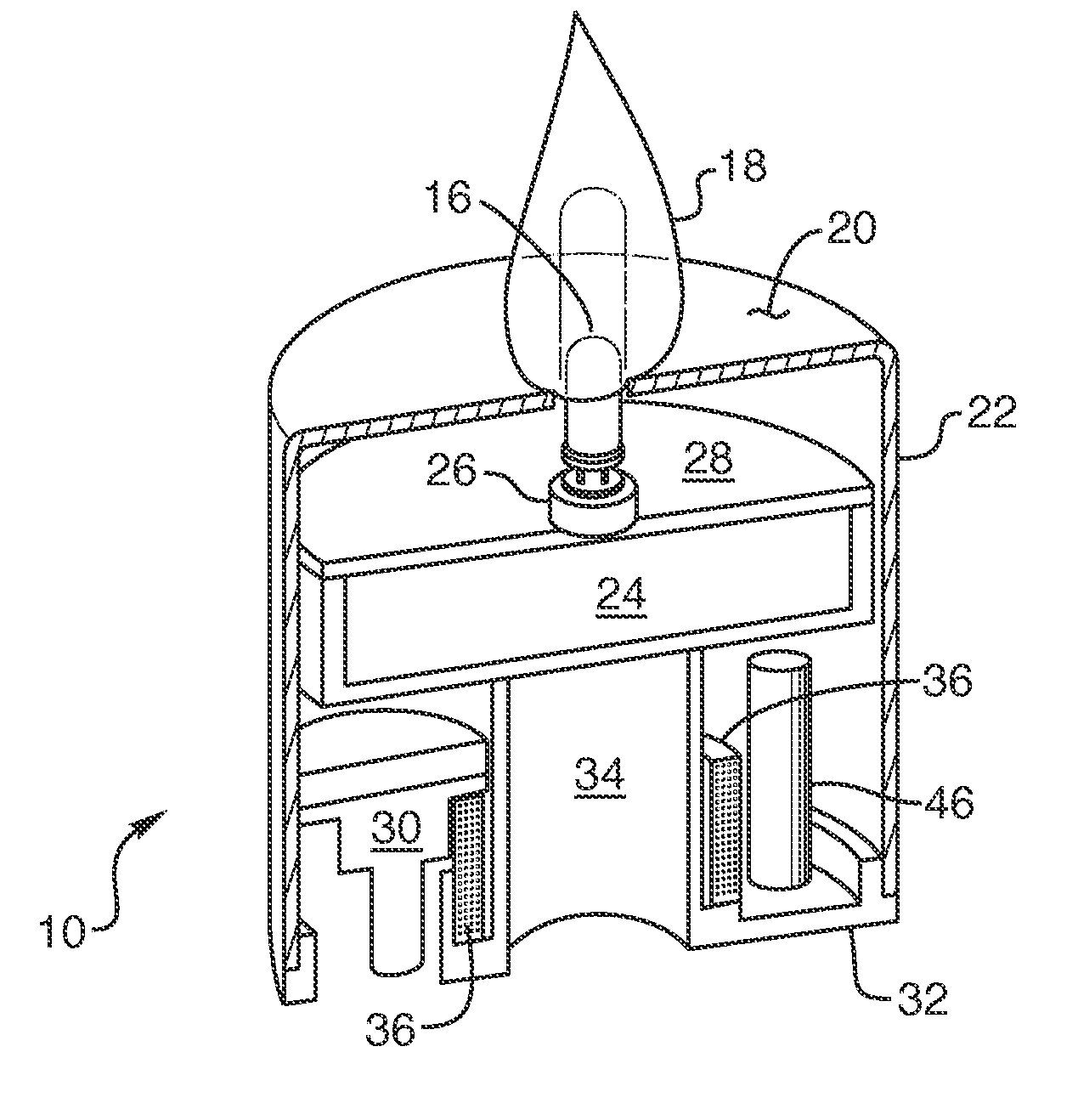
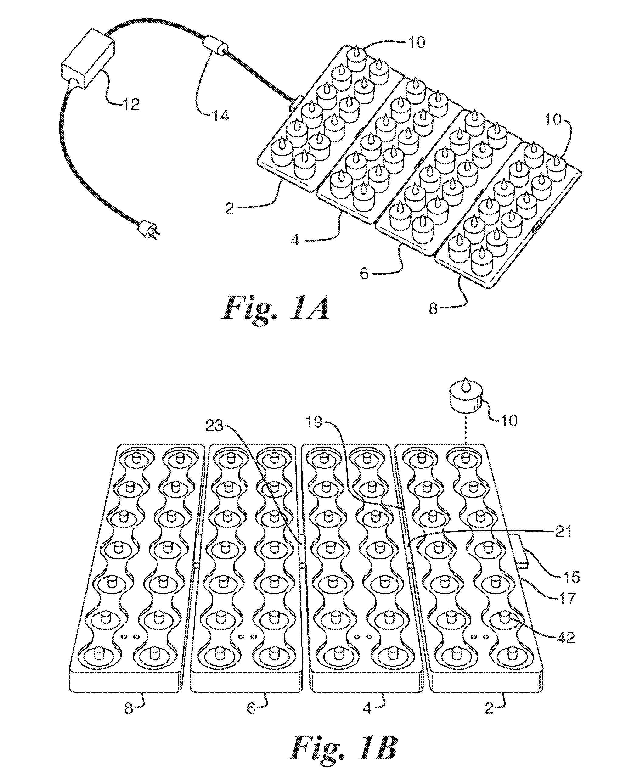
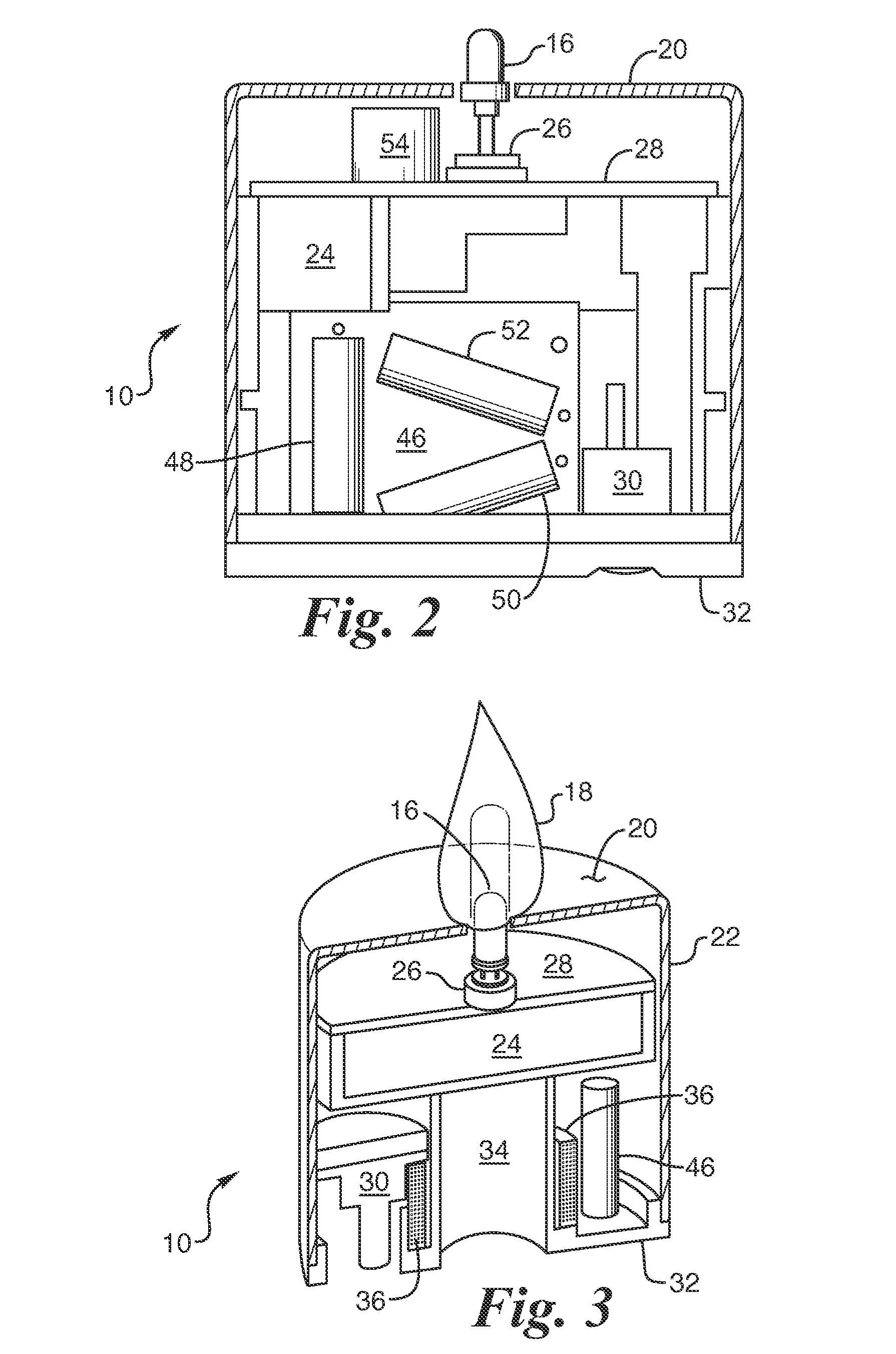
[0022]With reference to FIG. 1A, there is shown a plurality of electrically and mechanically interconnected artificial candle charging trays 2, 4, 6, 8 that are populated with a plurality of battery-operated artificial candles 10. Without limitation, each charging tray may hold up to a dozen artificial candles in which a rechargeable DC battery is connected through a semiconductor switch to a yellow LED and where the switch is, in turn, controlled by a programmed microprocessor chip such that the LED may be made to flicker much like the light given off by a real wax candle. Just how this is achieved will be explained in greater detail herein below.

[0023]With continued reference to FIG. 1A, power for the charging tray is derived from a conventional AC / DC adapter that when plugged into a wall socket at 110 volts produces a 12 volt DC output. Connected in the cable leading from the adapter 12 to the first recharging tray 2 is a current limiter circuit 14.

[0024]FIG. 1B illustrates the m...


PUM


Abstract

A large plurality of artificial, battery-operated, electronic candles are arranged to be simultaneously recharged upon placement on a series of interconnected charging trays that include a transformer primary winding at defined locations thereon. The primary windings are driven by an AC signal whose duty cycle is controlled by a pulse width modulator IC to induce a voltage across secondary windings contained within the candle housing. This induced signal is rectified to produce the battery charging current and the delivery of the charging current to the rechargeable batteries is controlled by a microprocessor IC.

Description

BACKGROUND OF THE INVENTION[0001]I. Field of the Invention[0002]This invention relates generally to electronic candles used to simulate actual wax candles, and more particularly to a system for recharging a large plurality of such candles.[0003]II. Discussion of the Prior Art[0004]There are artificial candles on the market presently that replicate the look of a burning wax candle, but which incorporate a yellow LED and a suitable electronic controller for imparting a flickering illumination of the LED to simulate the glow of a burning wax candle. However, for the most part, those candles embody a rechargeable battery and a circuit that had to be plugged into a DC current source to effect recharging of the candle, one at a time.[0005]Many restaurants often include a so-called votive candle on each table in the restaurant to add to the ambience of the place. A votive candle is generally 2.0 inches in height by 1.5 inches in diameter and is contained in a suitable holder, such as a gla...

Claims


Application Information

Patent Timeline
Patent Type & Authority Applications(United States)
IPC IPC(8): F21L4/00H05B44/00
CPCF21L4/08F21S6/001F21S9/02Y10S362/81F21L2/00F21W2121/00F21Y2101/02F21Y2115/10H05B45/10H05B45/50H05B45/325H02J50/10F21V23/026F21S10/04F21V3/02F21V23/04F21S10/046
Inventor HAU, DANIELCOWLEY, TIMVAIL, SHANE
Owner L&L CANDLE CO LLC
Why Eureka
Try Eureka