Configurable reset circuit for a phase-locked loop

a phase-locked loop and reset circuit technology, applied in the field of electrical and electronic arts, can solve the problems of not allowing the pll to maintain synchronization with the incoming signal, the performance the circuit of the pll is not good, so as to achieve the effect of eliminating the occurren

Inactive Publication Date: 2010-05-20
AVAGO TECH WIRELESS IP SINGAPORE PTE
View PDF2 Cites 0 Cited by
  • Summary
  • Abstract
  • Description
  • Claims
  • Application Information

AI Technical Summary

Benefits of technology

[0007]Illustrative embodiments of the present invention meet the above-noted need by providing circuits, methods and techniques for advantageously detecting and advantageously eliminating the occurrence of runaway in a PLL, particularly over variations in PVT conditions to which the PLL may be subjected.
[0008]In accordance with one aspect of the invention, a method of eliminating a runaway condition in a PLL includes the steps of: determining whether the PLL is locked to an input reference signal; when the PLL is not locked to the input reference signal, determining whether a frequency of an output signal generated by the PLL exceeds a prescribed maximum frequency; and when the frequency of the output signal generated by the PLL exceeds the prescribed maximum frequency, resetting the PLL to thereby eliminate the runaway condition.
[0009]In accordance with another aspect of the invention, a circuit for eliminating a runaway condition in a PLL includes a detector and at least one controller coupled to the detector. The detector is operative to receive a signal representative of an output signal of the PLL and to generate a signal indicative of a difference between a prescribed maximum frequency and a frequency of the signal representative of an output signal of the PLL. The controller is operative: to determine whether the PLL is locked to an input reference signal; when the PLL is not locked to the input reference signal, to determine whether the frequency of the signal representative of an output signal of the PLL exceeds the prescribed maximum frequency; and, when the frequency of the signal representative of an output signal of the PLL exceeds the prescribed maximum frequency, to reset the PLL to thereby eliminate the runaway condition.
[0010]In accordance with yet another aspect of the invention, an electronic system includes a PLL operative to receive an input reference signal and to generate an output signal having a frequency which substantially tracks a frequency of the input reference signal, and a configurable reset circuit coupled to the PLL and operative to eliminate a runaway condition in the PLL. The circuit includes a detector operative to receive a signal representative of an output signal of the PLL and to generate a signal indicative of a difference between a prescribed maximum frequency and a frequency of the signal representative of an output signal of the PLL. The circuit further includes at least one controller coupled to the detector. The controller is operative: to determine whether the PLL is locked to an input reference signal; when the PLL is not locked to the input reference signal, to determine whether the frequency of the signal representative of an output signal of the PLL exceeds the prescribed maximum frequency; and, when the frequency of the signal representative of an output signal of the PLL exceeds the prescribed maximum frequency, to reset the PLL to thereby eliminate the runaway condition.

Problems solved by technology

Generally, the larger the tracking range of the PLL, the worse is the performance of the PLL.
However, a narrow tracking range does not allow the PLL to maintain synchronization with the incoming signal over fluctuations in the frequency of the incoming signal, in addition to variations in operating conditions and / or manufacturing characteristics to which the PLL may be subjected, such as, for example, process, voltage supply and / or temperature (PVT).
A problem exists in the use of PLL circuits for certain applications, such as, for example, frequency multiplication, wherein the PLL output overshoots the targeted operating frequency and comes out of lock.
Unfortunately, over a range of PVT variations to which the PLL may be subjected, when this threshold for detecting a runaway condition is set too high, there is a significant risk that the occurrence of a runaway condition will never be detected.

Method used


Image

  • Configurable reset circuit for a phase-locked loop
  • Configurable reset circuit for a phase-locked loop
  • Configurable reset circuit for a phase-locked loop

Examples


Embodiment Construction

[0016]The present invention will be described herein in the context of an illustrative PLL circuit. It is to be appreciated, however, that the techniques of the present invention are not limited to the specific circuit shown and described herein. Rather, embodiments of the invention are directed broadly to improved techniques for detecting and eliminating runaway in a PLL circuit. For this reason, numerous modifications can be made to these embodiments and the results will still be within the scope of the invention. No limitations with respect to the specific embodiments described herein are intended or should be inferred.

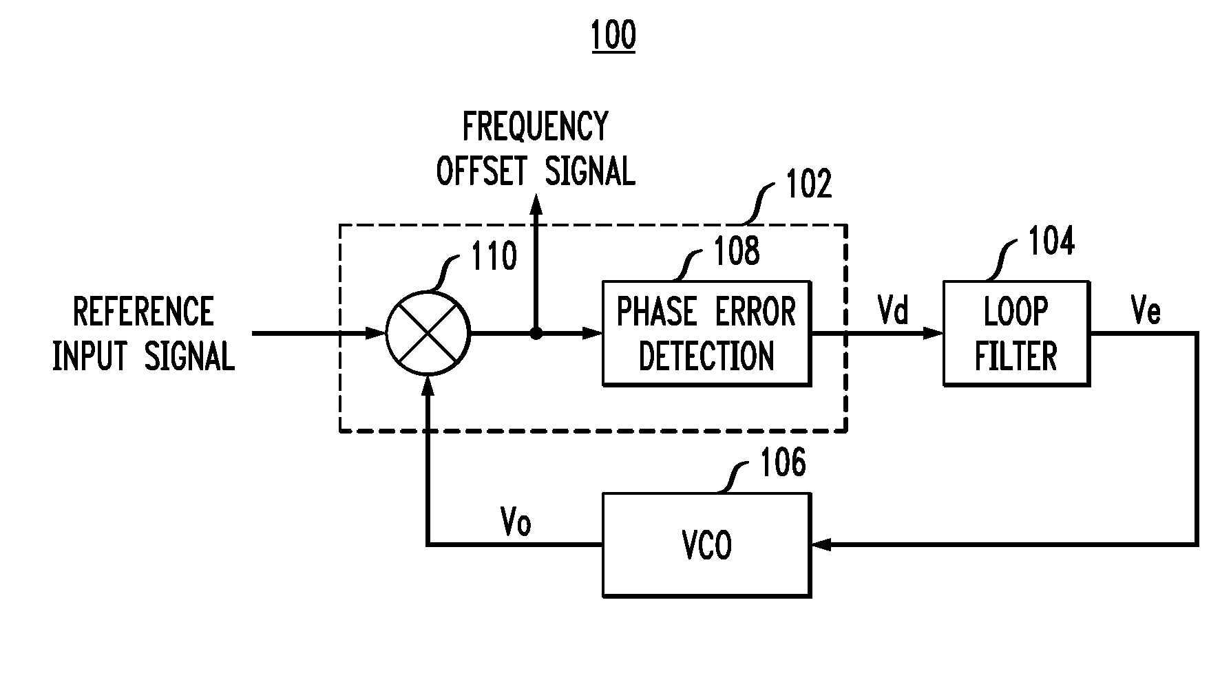
[0017]FIG. 1 is a block diagram depicting an exemplary PLL 100 in which techniques of the present invention may be implemented. The basic functional blocks of PLL 100 include a phase detector 102, or an alternative phase-frequency comparator, a loop filter 104 (e.g., low-pass filter, band-pass filter, etc.), and a voltage controlled oscillator (VCO) 106, or alterna...


PUM


Abstract

A method of eliminating a runaway condition in a PLL includes the steps of: determining whether the PLL is locked to an input reference signal; when the PLL is not locked to the input reference signal, determining whether a frequency of an output signal generated by the PLL exceeds a prescribed maximum frequency; and when the frequency of the output signal generated by the PLL exceeds the prescribed maximum frequency, resetting the PLL to thereby eliminate the runaway condition.

Description

FIELD OF THE INVENTION [0001]The present invention relates generally to the electrical and electronic arts, and more particularly relates to phased-locked loop (PLL) circuits.BACKGROUND OF THE INVENTION [0002]A PLL is a well-known frequency-selective feedback control system which is adapted to generate a signal that can synchronize with a reference input signal and closely track the frequency changes which may be associated with the input signal. PLLs are utilized in numerous applications, including, for example, communication, telemetry and data-recovery systems.[0003]The range of frequencies over which the PLL can maintain synchronization with an input signal is typically defined as the tracking range, or lock range, of the system. This is different from the range of frequencies over which the PLL can first synchronize with the incoming signal, the latter range of frequencies being typically known as the capture range, or acquisition range, of the PLL. The capture range is charact...

Claims


Application Information

Patent Timeline
Patent Type & Authority Applications(United States)
IPC IPC(8): H03K11/00
CPCH03L7/105H03L7/10Y10S331/02
Inventor SMITH, PAUL JEFFREYBRADFIELD, TRAVIS A.WHITT, JEFFREY K.
Owner AVAGO TECH WIRELESS IP SINGAPORE PTE
Why Eureka
Try Eureka