

Mini serial attached SCSI high density connector
- Summary
- Abstract
- Description
- Claims
- Application Information
AI Technical Summary
Benefits of technology
Problems solved by technology
Method used
Image

Examples
Embodiment Construction
[0031]The present invention will be apparent from the following detailed description, which proceeds with reference to the accompanying drawings, wherein the same references relate to the same elements.
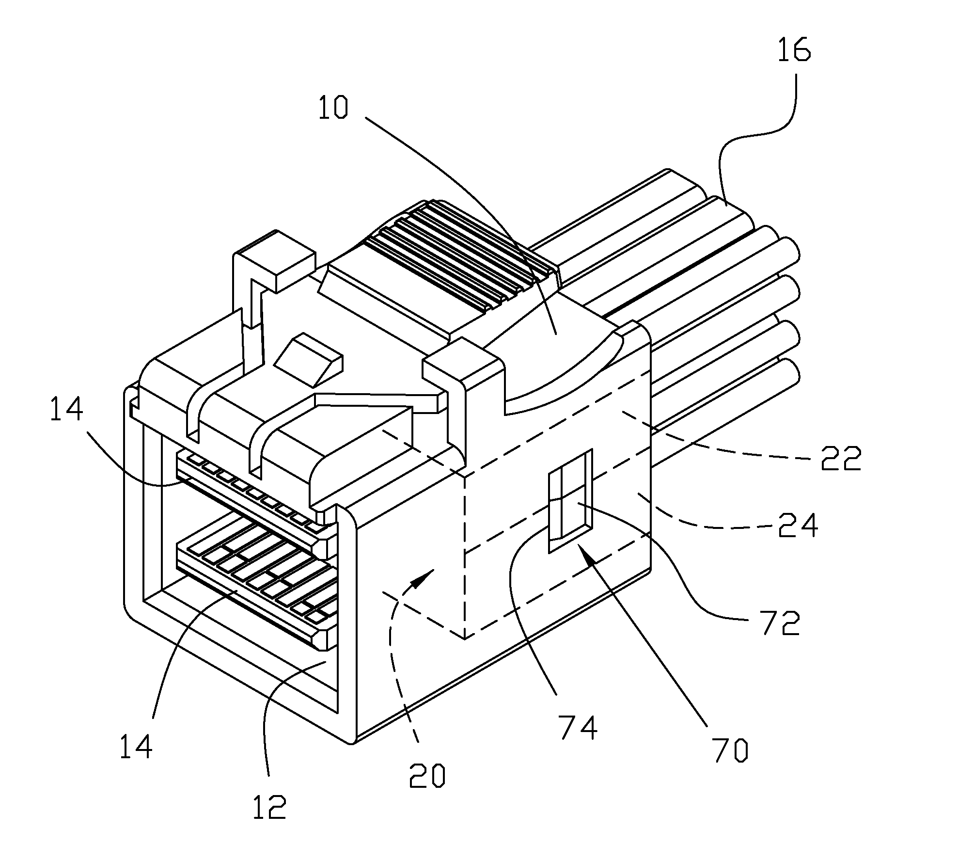
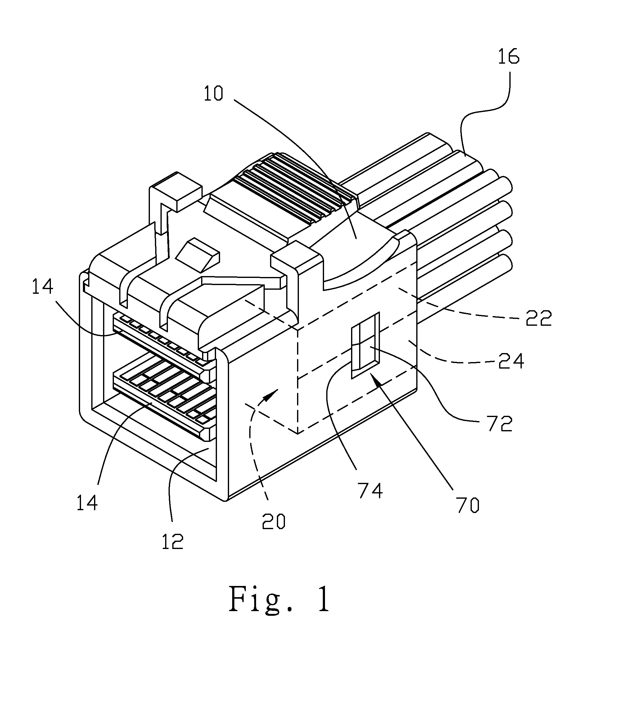
[0032]Referring to FIG. 1, a short-type mini SAS HD connector includes a front housing 10 and a rear housing 20. The front housing 10 has a frame structure, and an insertion space 12 in an axial direction. The rear housing 20 includes a first rear shell piece 22 and a second rear shell piece 24 combined together, and the rear housing 20 can be combined with a circuit board or circuit boards 14. The circuit board 14 can be combined with a cable 16. Furthermore, the rear housing 20 can be completely or almost completely inserted into the insertion space 12 of the front housing 10.
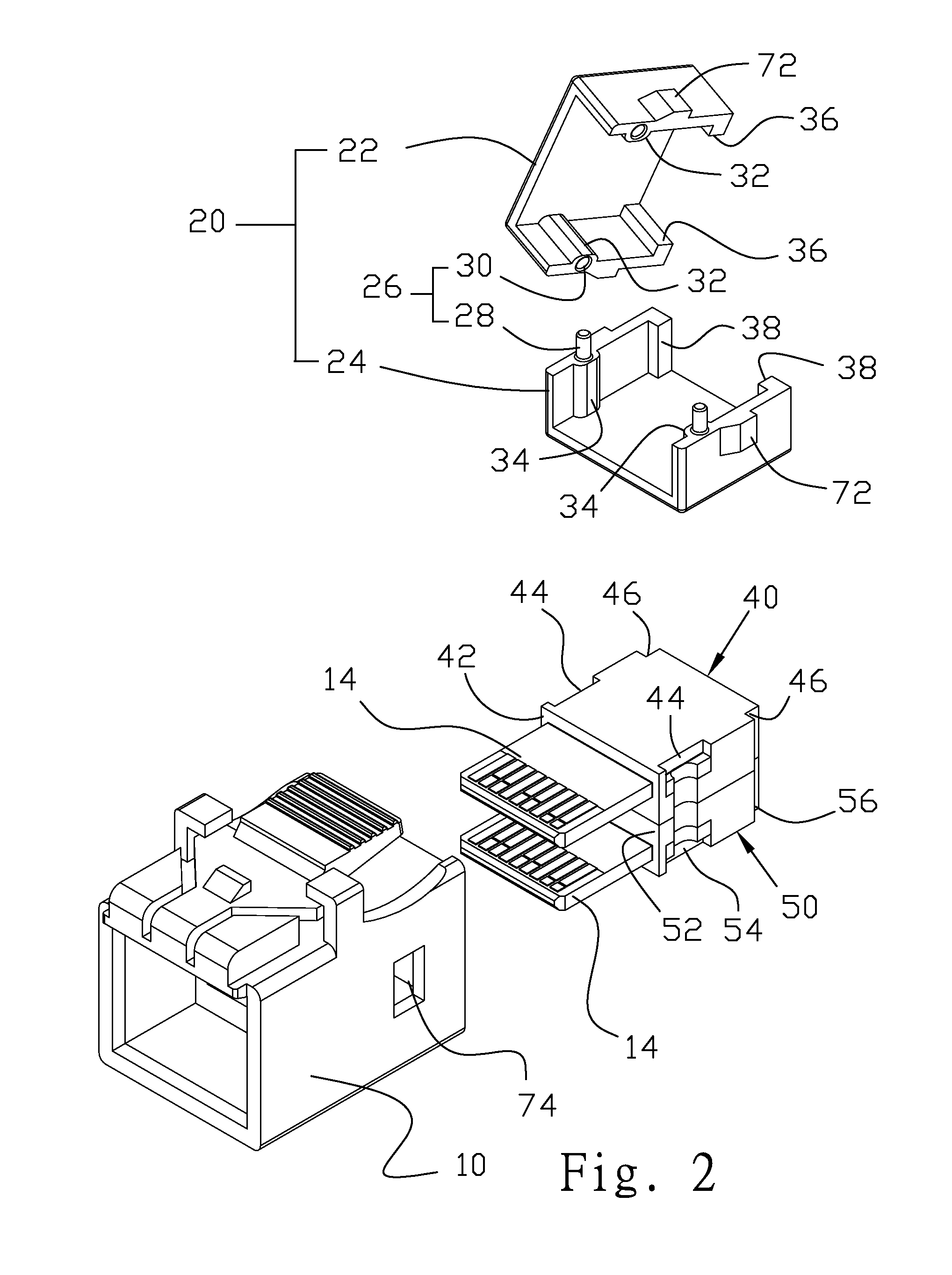
[0033]Referring to FIG. 2, a positioning mechanism 26 is further provided between the first rear shell piece 22 and the second rear shell piece 24. When the first rear shell piece 22 and the second rear shell p...
PUM
 Abstract
Description
Claims
Application Information