Braided Stent With a Shortenable Tether

a stent and tether technology, applied in the field of braided stents, can solve the problems of small deployment diameter, lack of radial strength to prop open the vessel, and significant re-narrowing of treated vessels

Inactive Publication Date: 2010-05-20
MEDTRONIC VASCULAR INC
View PDF12 Cites 67 Cited by
  • Summary
  • Abstract
  • Description
  • Claims
  • Application Information

AI Technical Summary

Problems solved by technology

Soon after the procedure, however, a significant proportion of treated vessels re-narrow.
Unfortunately, braided polymer stents often undergo plastic relaxation in the delivery system, leading to a smaller deployment diameter.
They also often lack the radial strength to prop open the vessel and maintain a fixed position in the vessel lumen.
Unfortunately, this increases the crossing profile of the compressed stent, reducing maneuverability and the ability to deploy the stent in smaller vessels.
Unfortunately, the elastomeric runners can cause problems during storage and deployment.
During storage, the elastomeric runners constantly exert force on the braided fiber body, which can permanently distort the braided fiber body.
The elastomeric runners can also lose their elasticity with age and the constant loading and become ineffective.
During deployment, the elastomeric runners exert force on the braided fiber body as the braided stent leaves the compressing sheath, so placement of the expanding braided stent is difficult.

Method used


Image

  • Braided Stent With a Shortenable Tether
  • Braided Stent With a Shortenable Tether
  • Braided Stent With a Shortenable Tether

Examples


Embodiment Construction

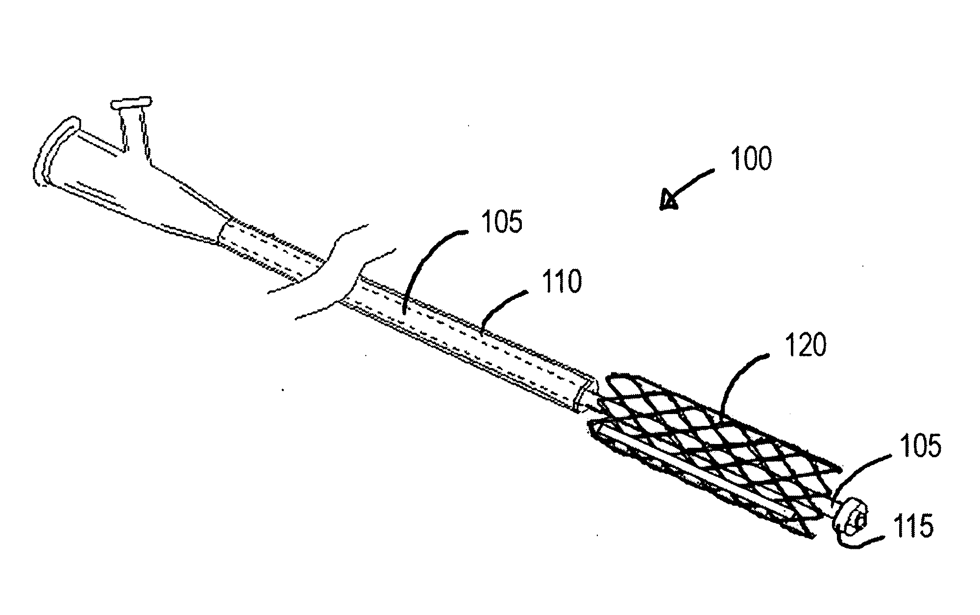
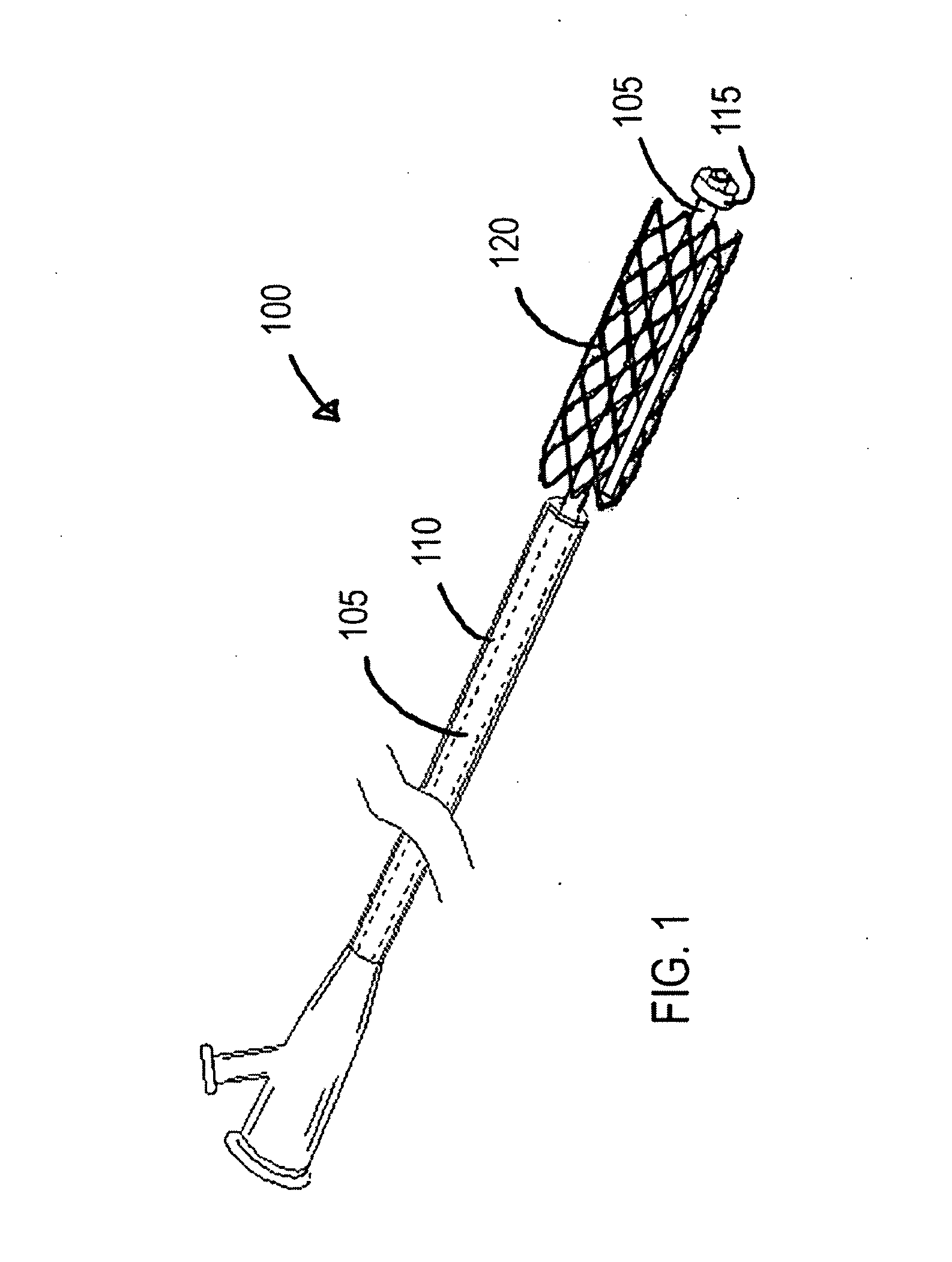
[0017]FIG. 1 is a perspective view of a stent delivery system made in accordance with the present invention. In this example, the stent has been advanced from the sheath as it would be for deployment in a vessel. The stent delivery system 100 includes a catheter 105, and a stent 120 disposed on the catheter 105. In one embodiment, a sheath 110 is included in the stent delivery system 100 and the sheath 110 is disposed about the stent 120 to maintain the stent 120 in a compressed state for delivery to the deployment site. In another embodiment, the sheath 110 is omitted and the stent 120 is maintained in the compressed state due to materials or other means of compressing the stent 120. In one embodiment, the catheter 105 can include a retainer 115, such as mechanical or adhesive structures, for retaining the stent 120 on the catheter 105 until the stent 120 is deployed.

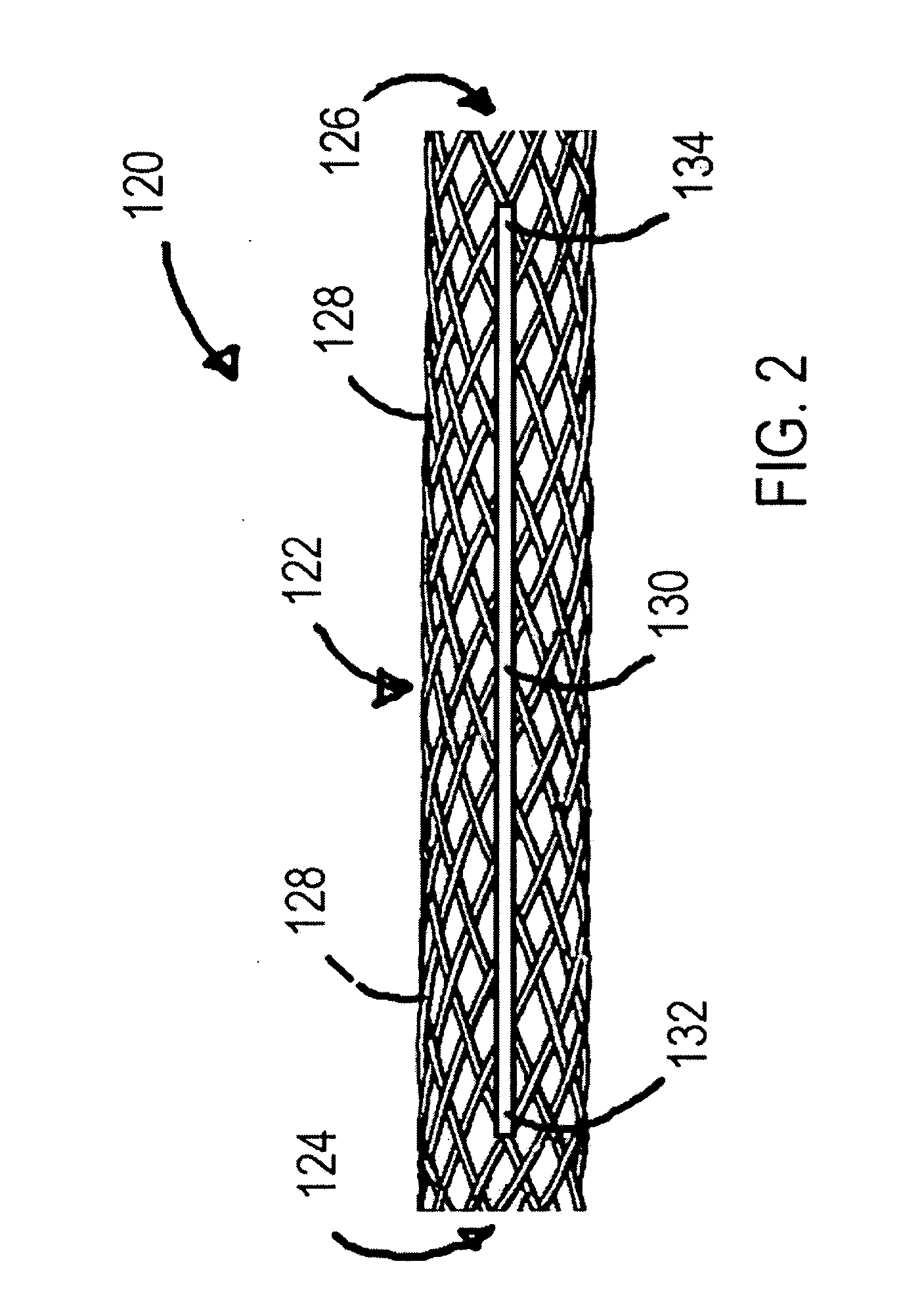
[0018]The stent 120 can be any variety of braided implantable prosthetic devices known in the art. In one embodiment...


PUM


Abstract

The braided stent with a shortenable tether of the present invention includes a stent for use in a vessel having a vessel wall including a braided stent framework having a first framework end and a second framework end; and a plurality of shortenable tethers, each of the plurality of shortenable tethers having a first tether end and a second tether end, the plurality of shortenable tethers being disposed along a length of the braided stent framework and fixed to the braided stent framework at the first tether end and the second tether end. The plurality of shortenable tethers shorten in response to vessel conditions to urge the first framework end and the second framework end toward each other when the stent is deployed in the vessel to urge a circumference of the braided stent framework toward the vessel wall.

Description

TECHNICAL FIELD[0001]The technical field of this disclosure is medical implant devices, particularly, braided stents.BACKGROUND OF THE INVENTION[0002]Stents are generally cylindrical shaped devices that are radially expandable to hold open a segment of a blood vessel or other anatomical lumen after implantation into the body lumen. Stents have been developed with coatings to deliver drugs or other therapeutic agents.[0003]Stents are used in conjunction with balloon catheters in a variety of medical therapeutic applications including intravascular angioplasty. For example, a balloon catheter device is inflated during PTCA (percutaneous transluminal coronary angioplasty) to dilate a stenotic blood vessel. The stenosis may be the result of a lesion such as a plaque or thrombus. After inflation, the pressurized balloon exerts a compressive force on the lesion thereby increasing the inner diameter of the affected vessel. The increased interior vessel diameter facilitates improved blood f...

Claims


Application Information

Patent Timeline
Patent Type & Authority Applications(United States)
IPC IPC(8): A61F2/86A61F2/82A61F2/90
CPCA61F2/90A61F2002/825A61F2/95
Inventor KALSTAD, MEGANGUO, YA
Owner MEDTRONIC VASCULAR INC
Why Eureka
Try Eureka