
Trial implant and method of use

a technology of implant and tibia, applied in the field of implants, can solve the problems of difficult to determine the exact size and orientation of the permanent tibial implant, difficult to test the exact size and orientation of the implant, and easy damage to the polymer material of the inser

Active Publication Date: 2010-05-20
HOWMEDICA OSTEONICS CORP
View PDF11 Cites 62 Cited by
  • Summary
  • Abstract
  • Description
  • Claims
  • Application Information

AI Technical Summary

Benefits of technology

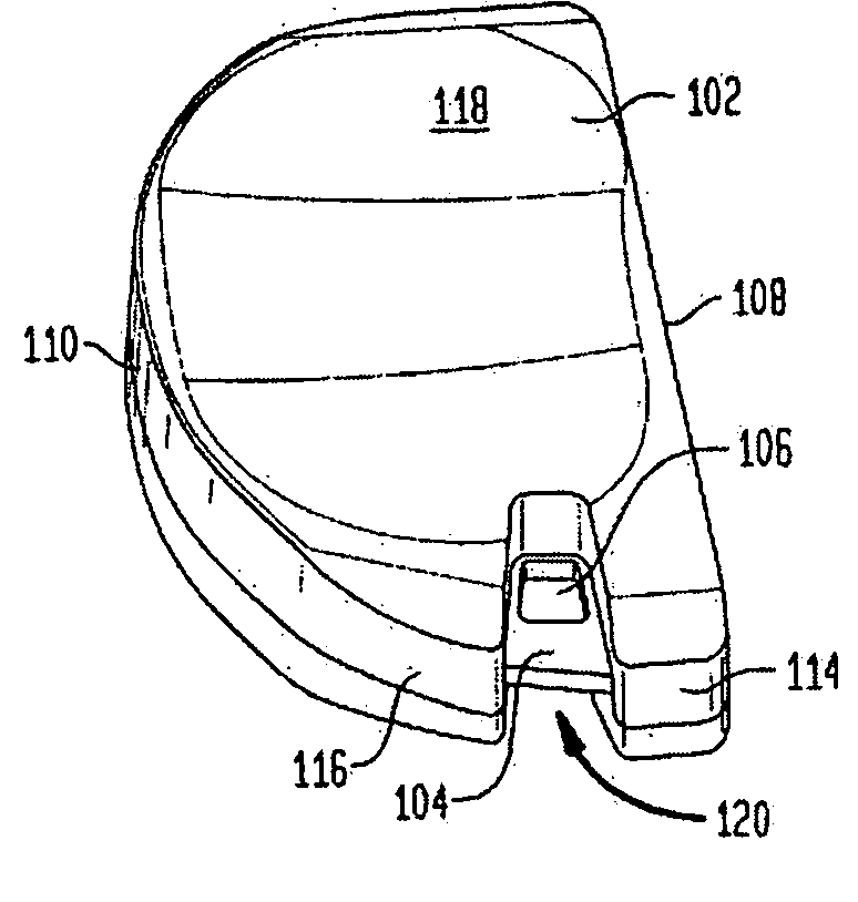
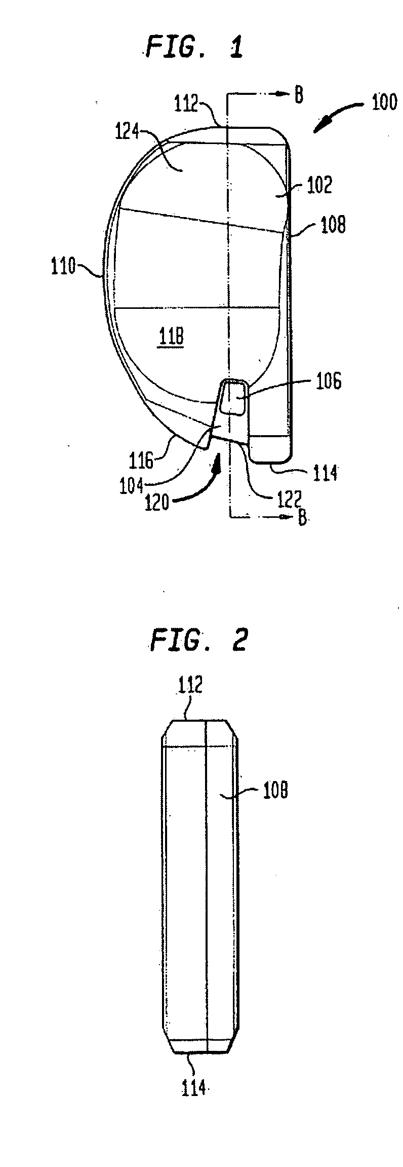
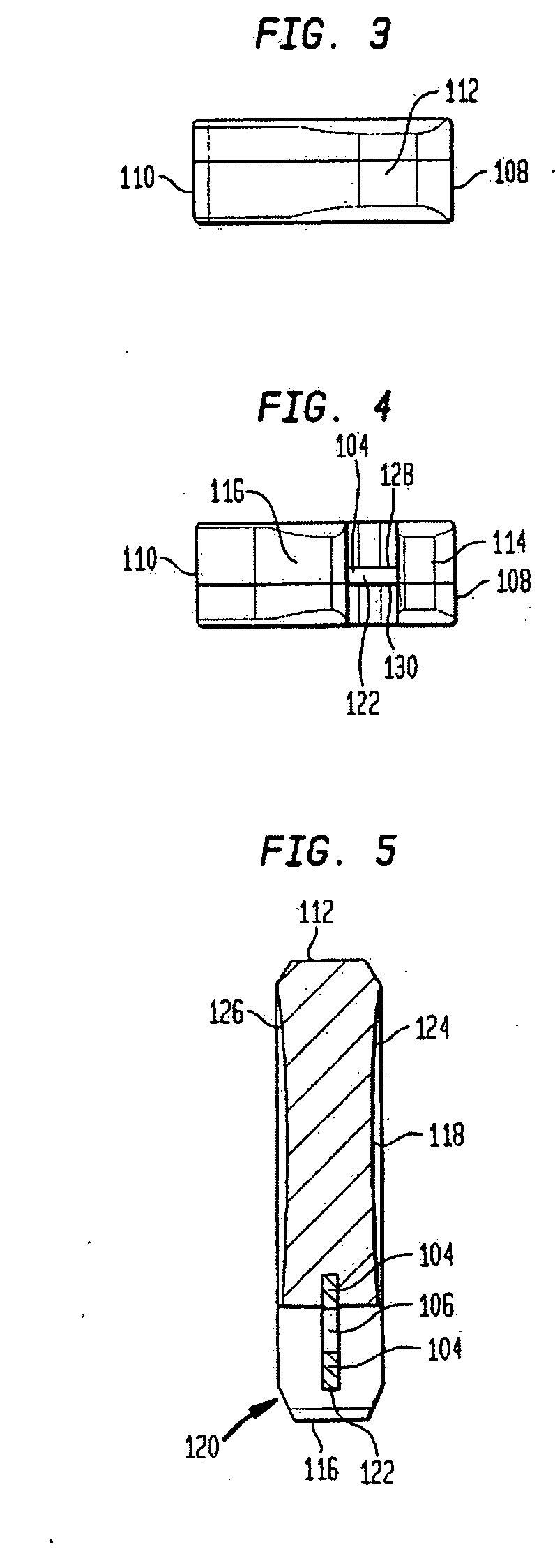
[0008]A first aspect of the present invention is a trial implant comprising a body and a tab disposed within the body. In accordance with one embodiment of this first aspect, the body may be sized to closely approximate the dimensions of a permanent implant...

Problems solved by technology

It can often be difficult to determine the exact size and orientation of the permanent tibial implant prior to actually performing the surgical procedure.
As a surgical tool is often used to attach to and manipulate each insert, the polymeric material of the insert can be easily damaged during the trialing procedure.
This can lead to portions of the polymeric material being inadvertently introduced into the body of the patient.
Moreover, because sets of trial implants can be reused, individual inserts are often damaged to a point where they are no longer functional and must be replaced before future surgeries can be conducted.
The replacement of certain inserts and the acquisition of a dedicated instrument make these existing sets costly.
Another drawback with existing trial implants is that a surgical tool must attach to the implants on their exterior surfaces, and often times their bearing surfaces.
This leads to contact between the surgical tool and the anatomy surrounding the implantation site that may be unintentional, but is often unavoidable.
Such contact can cause damage to the surrounding bone and tissue, and furthermore, may hinder a surgeon's ability to adequately position the implant.

Method used


Image

  • Trial implant and method of use
  • Trial implant and method of use
  • Trial implant and method of use

Examples


Embodiment Construction

[0027]As used herein, when referring to bones or other parts of the body, the term “proximal” means closer to the heart and the term “distal” means more distant from the heart. The term “inferior” means toward the feet and the term “superior” means towards the head. The term “anterior” means towards the front part of the body or the face and the term “posterior” means towards the back of the body. The term “medial” means toward the midline of the body and the term “lateral” means away from the midline of the body.

[0028]Although the background of the invention section sets forth a discussion of a typical knee joint operation, it is understood that drawbacks associated with existing implants and surgical procedures are applicable to other joints in the human body, including the shoulder and the hip. Although the following description will generally be set forth in connection with knee joint implants and procedures, it is to be understood that the present invention is applicable to oth...


PUM


Abstract

Disclosed is a trial implant having a body and a tab. The body may include a recess and may be sized to closely approximate a permanent implant. The tab may be more durable than the body, and may be disposed within the body and wholly contained within the recess. Also disclosed is a method of performing a trialing procedure including providing a trial implant as described, providing a tool to attach to the tab, inserting the implant onto a resected joint, evaluating and extracting the implant. The same procedure may then be performed with a second implant. The method may further include a tool having an attachment portion that is substantially or wholly contained within the recess. A kit is disclosed including a plurality of trial implants of incrementally different shapes and sizes. The kit may further include a tool. Also disclosed is a method of making the described implant.

Description

BACKGROUND OF THE INVENTION[0001]The present invention is directed to implants, and more particularly to trial implants that are durable and easy to manipulate.[0002]Orthopedic procedures generally involve the resection of a bone, a trialing step to determine the proper size of a permanent implant, and implantation of the permanent implant. For instance, it has long been known in the art for orthopedic procedures involving the knee to include the resection of one or both tibial condyles, or portions thereof. The resection itself generally entails cutting and removing at least a portion of the proximal end of a tibial condyle and replacing same with a permanent tibial implant, which is typically comprised of a base plate and an insert. This type of knee surgery may be necessitated by a fracture or other deterioration of the tibial bone (as well as corresponding femoral bone). As such, the permanent tibial implant is used to improve or restore the normal functionality of the knee join...

Claims


Application Information

Patent Timeline
IPC IPC(8): A61F2/38A61F2/36A61B19/00
CPCA61F2/38A61F2/3859A61F2/3877A61F2002/4619A61F2/4684A61F2002/30616A61F2/389
Inventor GRECCO, JOHN JUDEMCMILLEN, TROY ALLEN
Owner HOWMEDICA OSTEONICS CORP
Learn More