Cyclone separator

a cyclone separator and cyclone technology, applied in the direction of filtration separation, separation process, moving filter element filter, etc., can solve the problems of inability to implement configuration and classic cyclone design cannot be used

Active Publication Date: 2010-05-27
AIRBUS OPERATIONS GMBH
View PDF18 Cites 1 Cited by
  • Summary
  • Abstract
  • Description
  • Claims
  • Application Information

AI Technical Summary

Benefits of technology

[0005]The object of the invention is to at least partiall

Problems solved by technology

Under the given circumstances, this configuration cannot be implemented, since the input and output for the separated material have to lie at the same pressure level, because the mixture to be cleaned comes from the wastewater tank, and the separated material should be re

Method used


Image

  • Cyclone separator
  • Cyclone separator
  • Cyclone separator

Examples


Embodiment Construction

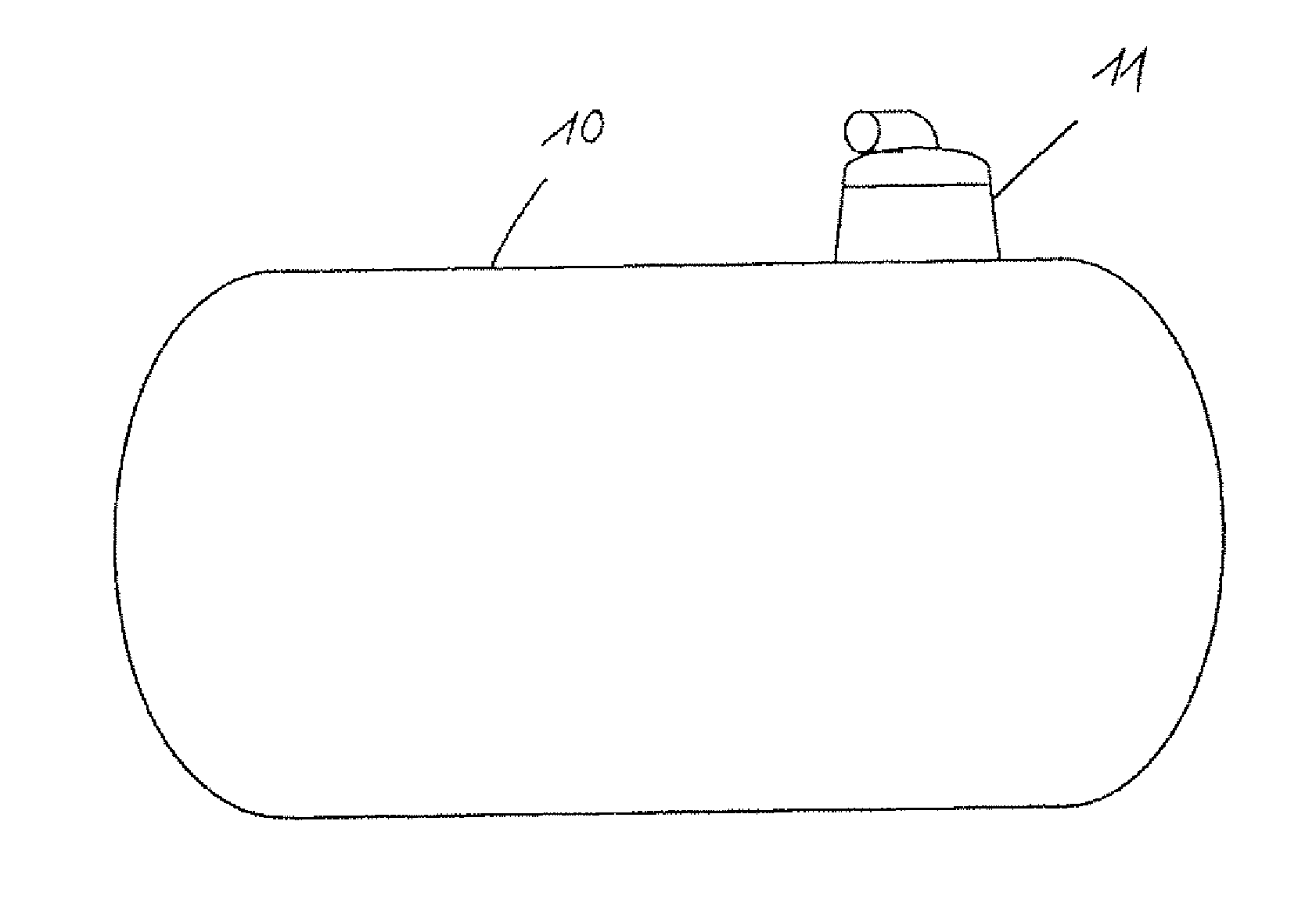
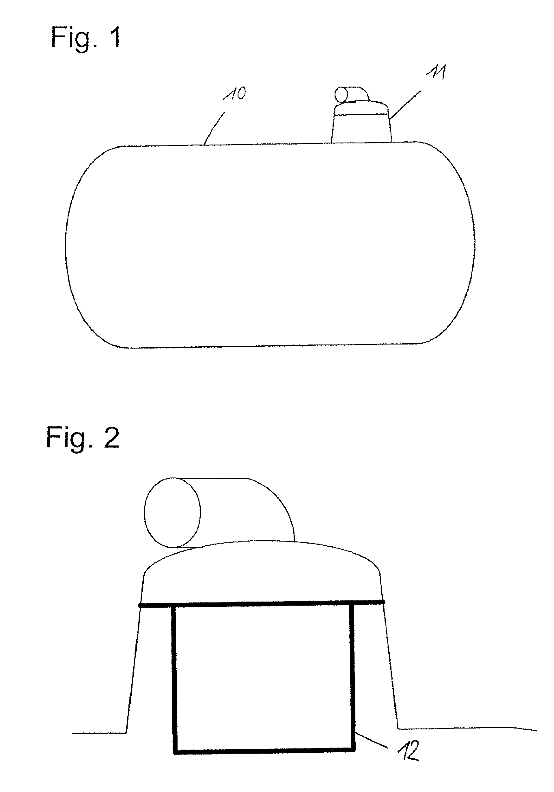
[0025]FIG. 1 shows a wastewater tank 10 of a vacuum toilet system. The wastewater tank 10 incorporates a separating device 11 that connects the wastewater tank 10 with the ambient air of the airplane by way of a pipe system. The object of the separating device 11 is to separate out the dispersed materials, liquid and solid constituents in the present embodiment, contained in the fluid streaming through, aerosol in the present case.

[0026]FIG. 2 shows a filter with a filter element 12 previously used as the separating device 11.

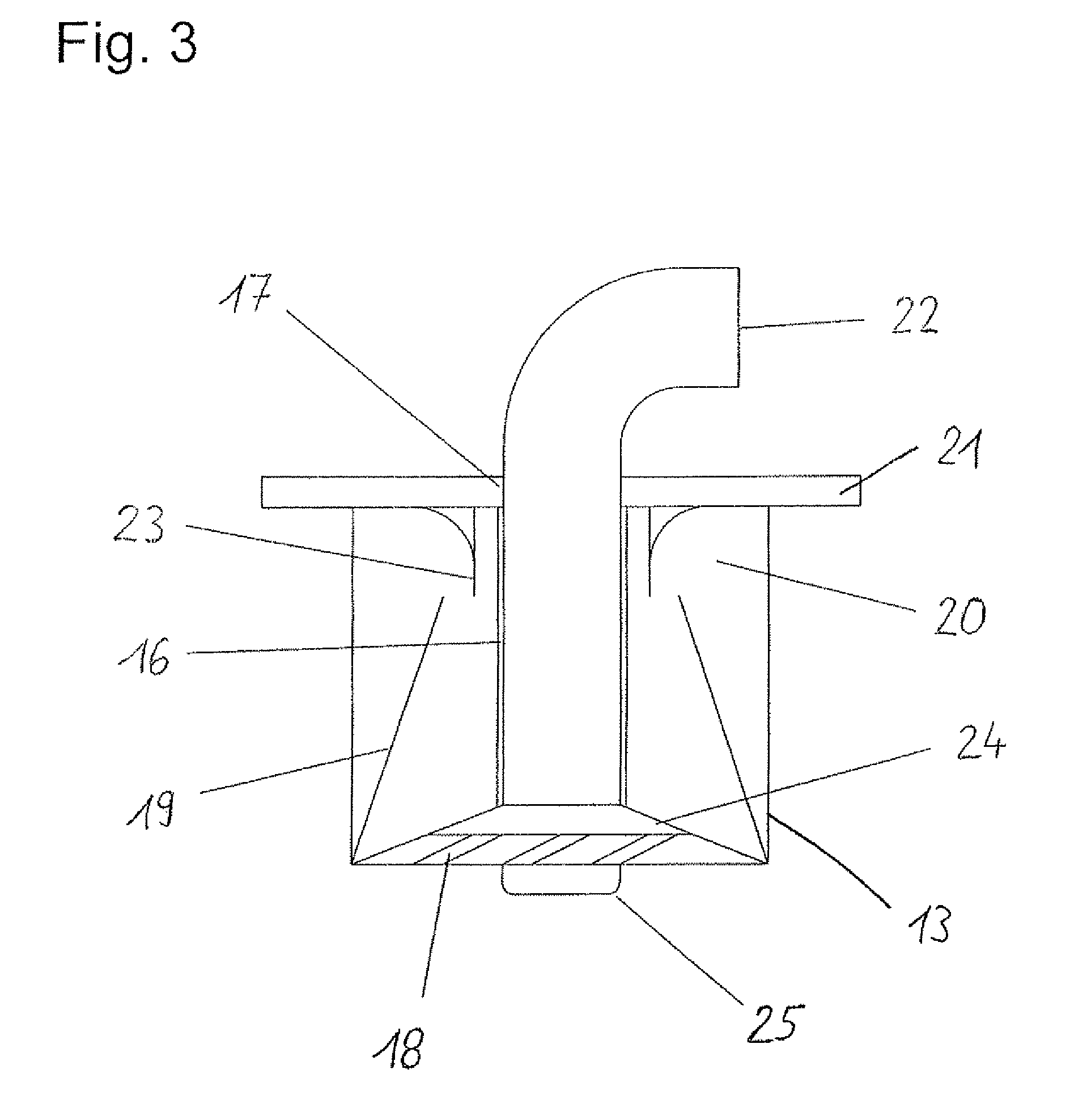
[0027]FIG. 3 shows the cyclone separator according to the invention in an embodiment of the invention. The cyclone separator according to the invention can be provided without modifications to the wastewater tank 10 in place of the filter shown in FIG. 2.

[0028]The cyclone separator exhibits a casing 13, which is designed in such a way that the cyclone separator fits in the design space of the previously used filter.

[0029]The input side of the cyclone separator ...


PUM

PropertyMeasurementUnit
Areaaaaaaaaaaa

Abstract

A preferred embodiment of the invention relates to a cyclone separator for a vacuum toilet system, with a casing; an input-side swirl generator, whose input openings impart a swirl to the inflowing fluid; a separating wall arranged in the casing, which encloses the fluid stream in the cyclone separator ring-like and whose interior cross section tapers downstream; and a collection tank in the casing for receiving and accumulating constituents separated out of the fluid. In addition, the invention relates to a wastewater tank and vacuum toilet system having such a cyclone separator.

Description

CROSS-REFERENCE TO RELATED APPLICATIONS[0001]This application claims the benefit of the filing date of U.S. Provisional Patent Application No. 61 / 200,102 filed Nov. 24, 2008, the disclosure of which application is hereby incorporated herein by reference.BACKGROUND OF THE INVENTION[0002]The invention relates to a cyclone separator for a vacuum toilet system, as well as a wastewater tank and a vacuum toilet system with such a cyclone separator.[0003]Vacuum toilet systems in aircraft utilize the pressure difference between the cabin pressure and a vacuum system—this is the outside pressure during air travel, and if the latter is not low enough, a pressure level produced by a vacuum generator—to convey the toilet contents into a wastewater tank. The low-pressure in the wastewater tank is ensured during air travel by a pipe running from the upper side of the tank toward the outer skin of the aircraft. The vacuum transport vigorously swirls the transported material. A portion of the trans...

Claims


Application Information

Patent Timeline
IPC IPC(8): E03D11/00B01D21/26
CPCB64D11/02C02F2201/001C02F2103/005C02F1/385
Inventor LUTZER, WILHELM
Owner AIRBUS OPERATIONS GMBH
Why Eureka
Try Eureka