
Method and apparatus for detecting a leak in a double pipe

a leakage detection and double pipe technology, applied in the direction of measuring devices, structural/machine measurement, instruments, etc., can solve the problem of leakage of molecules, and achieve the effect of improving the accuracy of the location

Inactive Publication Date: 2010-05-27
AREVA GMBH
View PDF11 Cites 24 Cited by
  • Summary
  • Abstract
  • Description
  • Claims
  • Application Information

AI Technical Summary

Benefits of technology

[0024]The measurement can be continuous, or else, according to the previous LEOS method, batch-wise. The first option has the advantage of simplified and quick monitoring; the latter option provides the advantage of recognizing the leak point from the temporal position of a concentration peak.
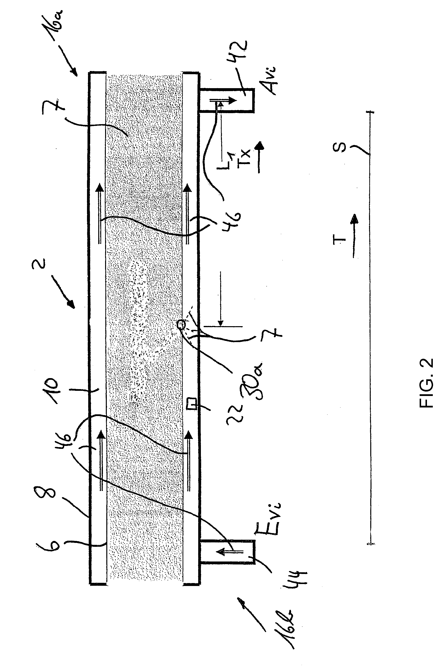
[0026]During transport of the leak molecules in the gap, the same principles of the superposition of fluid mechanics and diffusion are used, which results in an equalization of concentration differences in the circumferential direction and in maintenance of a relatively concentrated gas cloud during transport in the axial direction.
[0042]Once a leak has been detected, the medium can therefore also be moved from the first to the second end, and at the second end, the medium can be investigated for a substance which is characteristic of a leak, and a point of leak can then be ascertained using the transport time of the characteristic substance from the leak up to the second end and using the mass flow of the medium. This switch-over of the transport direction of the medium can also take place to and from a number of times in order to increase the location accuracy of the leak.
[0049]The accuracy of the location can be improved by calibrating using a test peak, as is known from LEOS, and using the mass flow measured at the inlet.

Problems solved by technology

Thus, if the substance is detected in the medium, leaked molecules are present.

Method used


Image

  • Method and apparatus for detecting a leak in a double pipe
  • Method and apparatus for detecting a leak in a double pipe
  • Method and apparatus for detecting a leak in a double pipe

Examples


Embodiment Construction

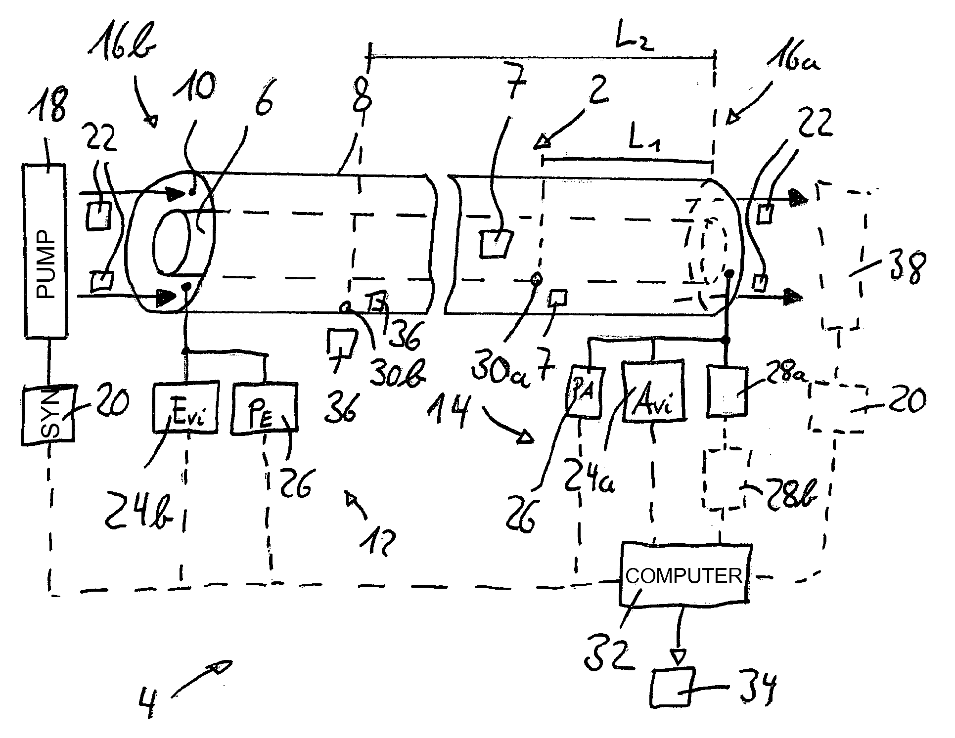
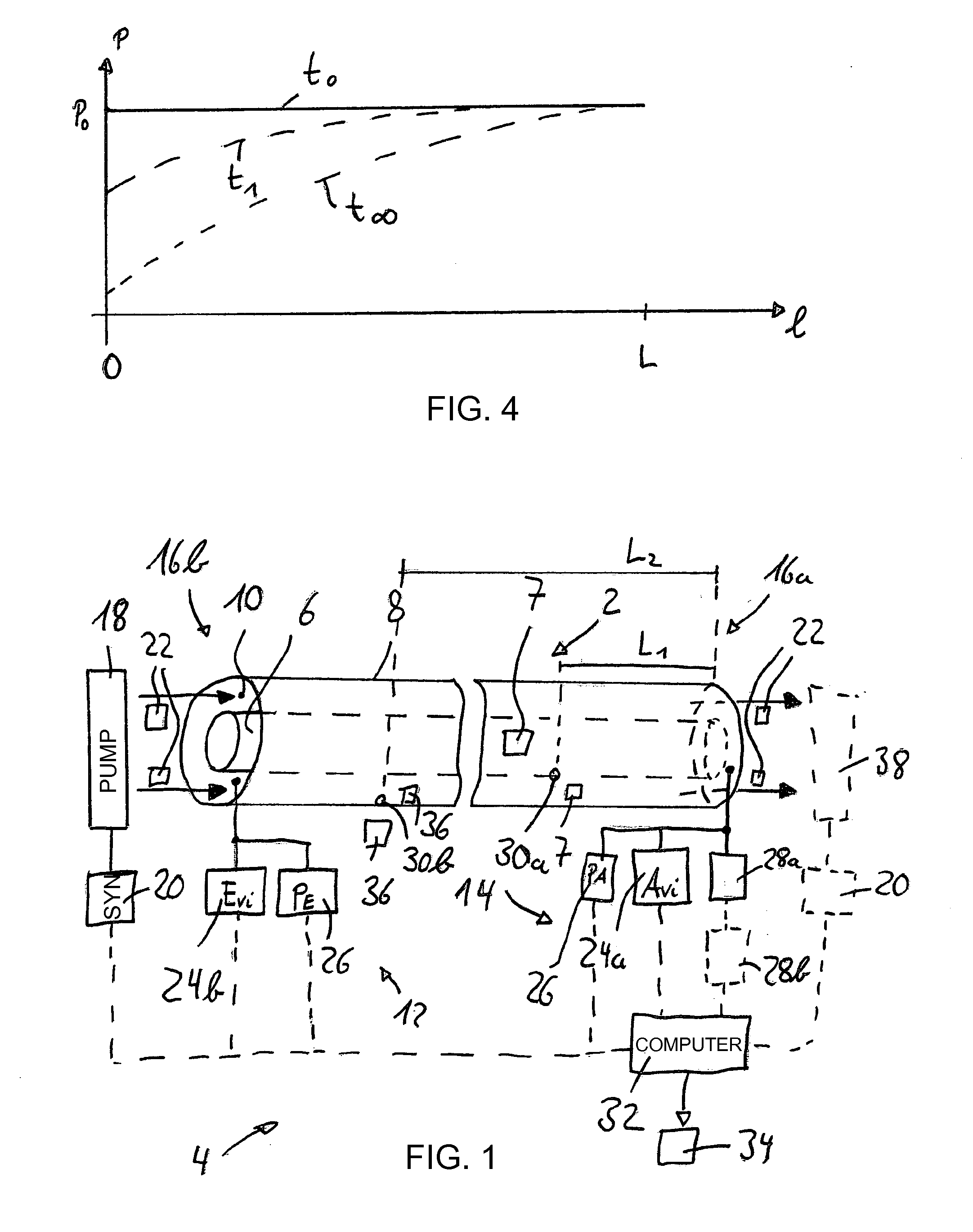
[0060]Referring now to the figures of the drawing in detail and first, particularly, to FIG. 1 thereof, there is shown a pipeline 2 with a system 4 arranged thereon for leak recognition and location. The pipeline 2 has a double-wall design, i.e. contains an internal pipe 6 for transporting a product 7, such as petroleum, and an external pipe 8 which encloses the former concentrically. The external pipe 8 surrounds the internal pipe 6 with a radial space or gap 10.

[0061]The system 4 contains a feed part 12 and an evaluation part 14. The evaluation part 14 is arranged at a first end 16a of the pipeline 2, the feed part 12 is arranged at the other end in the direction of extent, i.e. the second end 16b.

[0062]The feed part 12 contains a pressure pump 18, which is controlled by a system 20 for time synchronization. The pressure pump 18 is used to push measurement air 22 in the axial direction of the pipeline 2 into the gap 10 if the pressure pump 18 is active. The feed part 12 also cont...


PUM


Abstract

In a method for detecting a leak in a double pipe, a medium located in an intermediate chamber between the interior and exterior pipe is moved toward a first end of the pipe, whereupon the medium flows in from the second end. On the first end the medium is examined for any leakage of a characteristic material, upon the detection of which a leakage signal is generated and a location of the leakage is calculated based on the transport time of the characteristic material from the leakage to the first end and on the mass flow of the medium. A corresponding device contains a conveyor unit for moving the medium through the intermediate chamber. A material sensor is disposed at the first end for examining the medium for the characteristic material. A control and analysis unit is provided for generating a leakage signal and calculating the location of the leakage.

Description

CROSS-REFERENCE TO RELATED APPLICATION[0001]This is a continuation application, under 35 U.S.C. §120, of copending international application No. PCT / EP2008 / 006356, filed Aug. 1, 2008, which designated the United States; this application also claims the priority, under 35 U.S.C. §119, of German patent application No. 10 2007 036 682.7-54, filed Aug. 3, 2007; the prior applications are herewith incorporated by reference in their entirety.BACKGROUND OF THE INVENTIONField of the Invention[0002]The invention relates to a method and an apparatus for detecting a leak in a double pipe.[0003]Pipelines are used for transporting liquid or gaseous products, such as petroleum or natural gas, predominantly in the petroleum or chemical industry. Since the transported products are generally harmful to the environment, it is desirable for a leak in a pipeline to be detected as quickly as possible, i.e. to recognize it and / or locate it.[0004]In this respect, a system, sold under the trademark LEOS or...

Claims


Application Information

Patent Timeline
IPC IPC(8): G01M3/28
CPCG01M3/222
Inventor JAX, PETER
Owner AREVA GMBH
Learn More