Vehicle Gunner's Protection Cuppola

a technology for vehicle gunners and cuppolas, applied in shields, manufacturing tools, gun mountings, etc., can solve the problems of insufficient ballistic protection, physical wounds to body areas, and more dangerous and violent battlefields than ever before, and achieve uniform physical size, shape and weight, and increase survivability. the effect of minimal space requirements

Inactive Publication Date: 2010-05-27
CARTER PAUL
View PDF12 Cites 7 Cited by
  • Summary
  • Abstract
  • Description
  • Claims
  • Application Information

AI Technical Summary

Benefits of technology

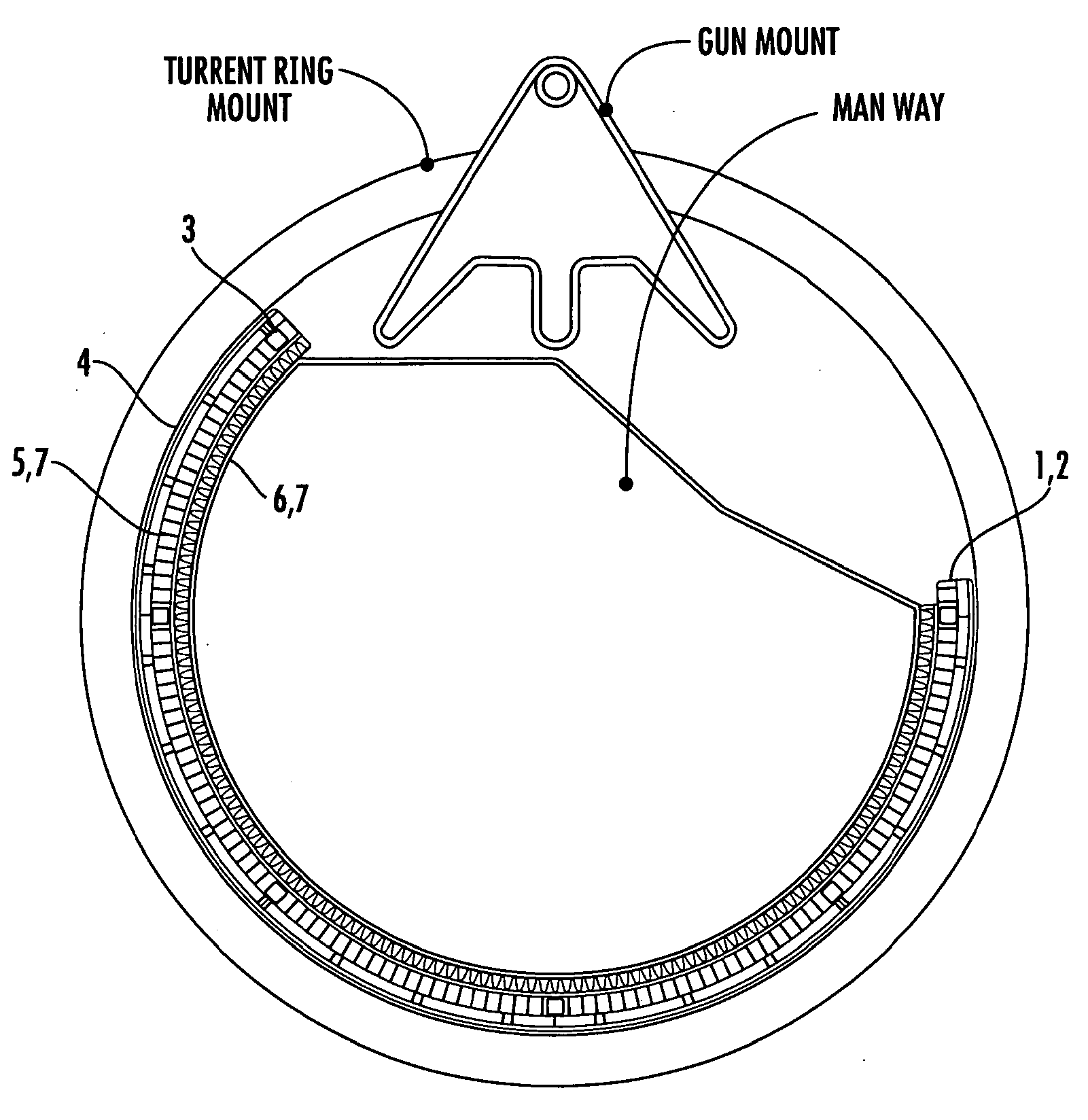
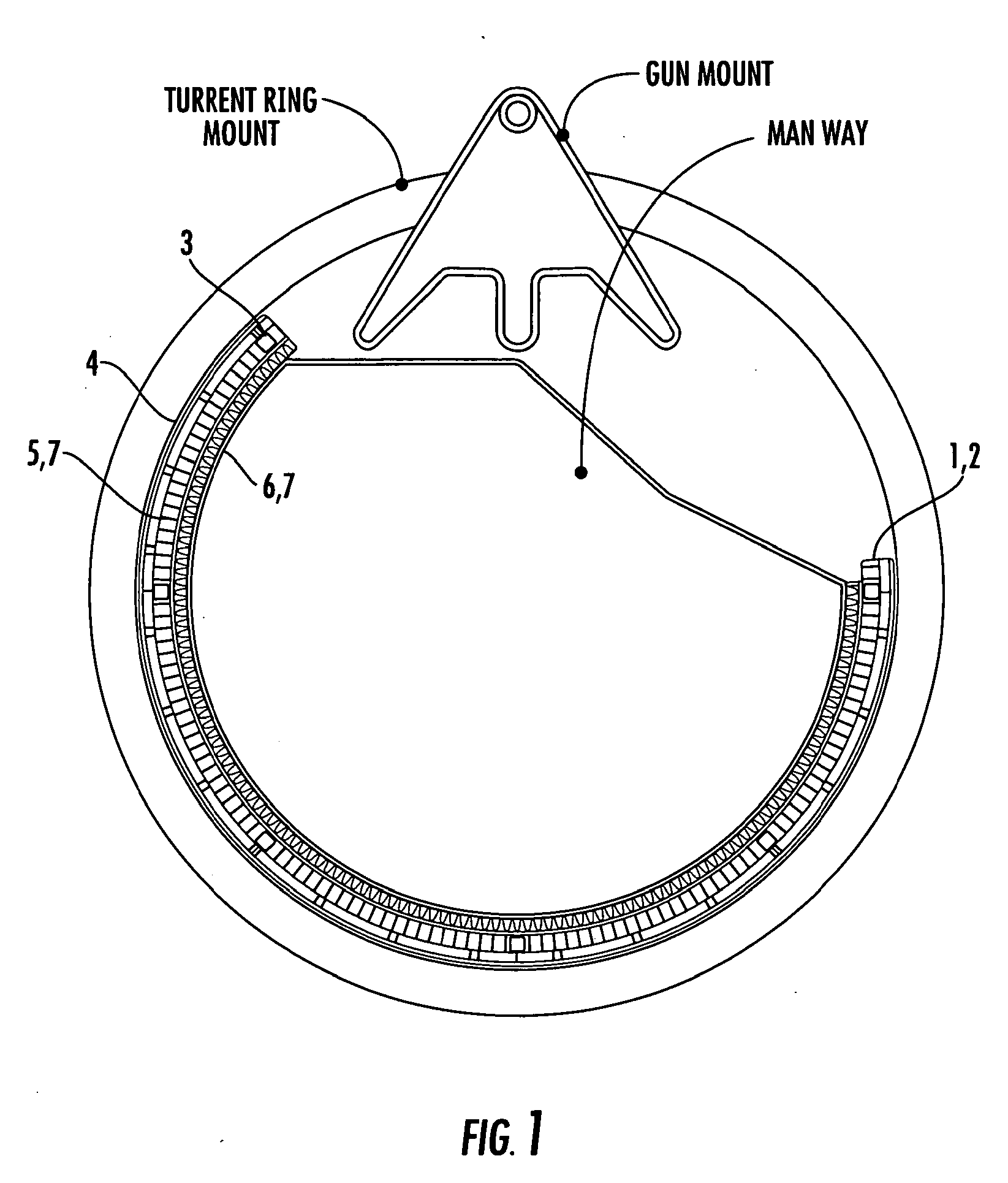
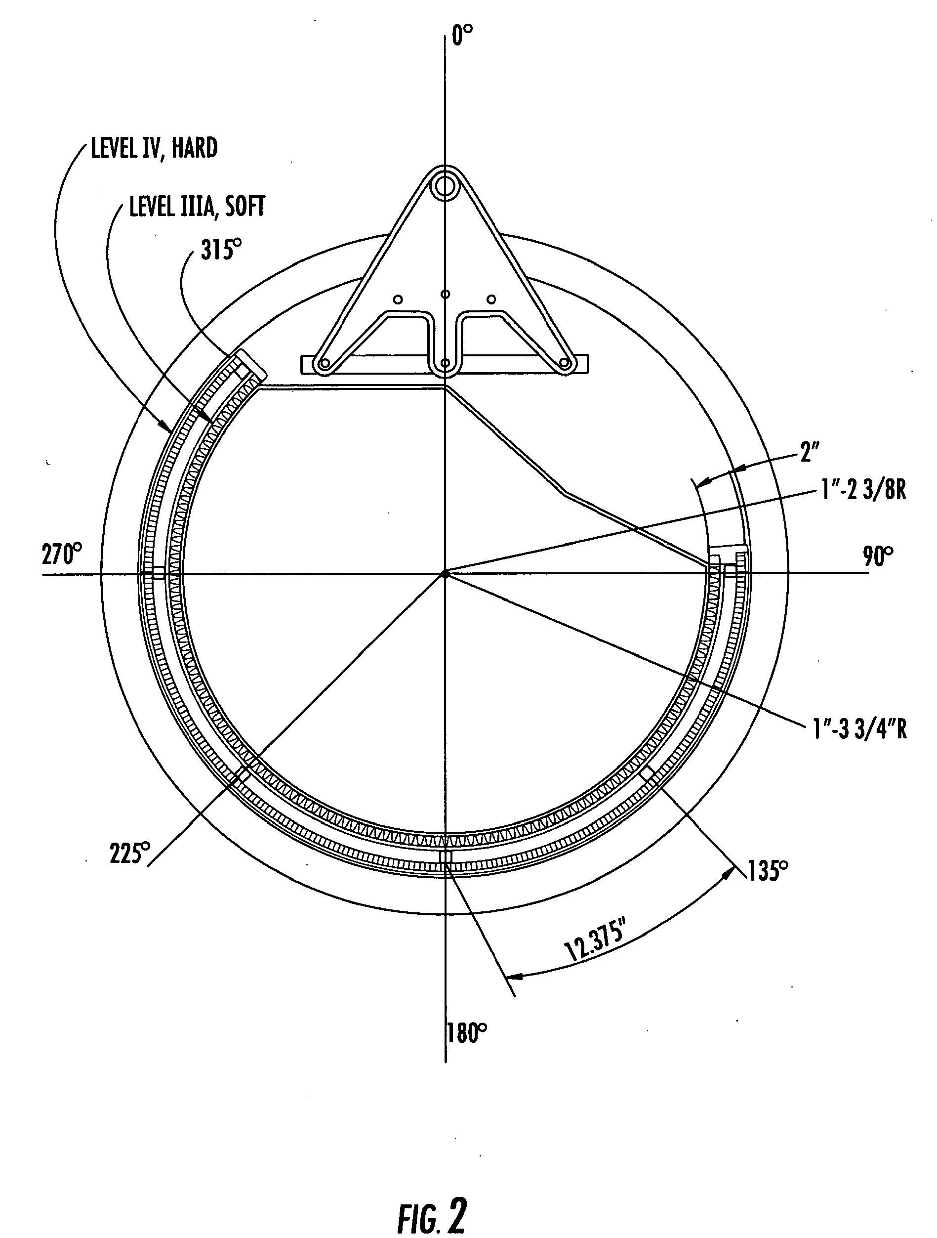
[0006]The present technology is configured to primarily provide rear and side ballistic, flame, and / or thermo-acoustic protection for the exposed or partially exposed vehicle occupant such as a gunner. The field assembled frame, ballistic protection segments, and fire and thermo-acoustic protection segments are designed to be installed to the roof mounted gun turret ring, providing mechanical stability and maneuverability for the gunner's operation of the mounted gun. The outer portion of the invention is comprised of contoured or fitted segments or plates constructed of a rigid or semi-rigid ballistic material. These segments are of relatively uniform physical size, shape and weight. These segments are inserted into receiving frame segments and are secured with fastening devices. These segments provide the primary ballistic protection. The interior portion of this invention is comprised of pliable thermally resistant and acoustical dampening materials fitted into segments matching or “backing” the rigid or semi-rigid ballistic material. The innermost portion of the invention is comprised of pliable ballistic material contained within an outer carrier constructed of a pliable, abrasion, moisture, and flame resistant quick drying material capable of accepting various Camouflage design patterns. This innermost portion of the invention provides protection for the gunner while engaged in tasks that subject the gunner to discomfort caused by contact with heat laden metals, impacts or pressure, and acoustical trauma. The end product is a modular, configurable, field assembled and installed device that is designed to defeat small arms and IED attacks, and to increase survivability after sustaining fire, thermo-acoustical, and ballistically undefeatable injuries.
[0007]The entire device can be logistically delivered with minimal space requirements, field configured and assembled, installed, and / or repaired. The device dimensions are proportionally modified to achieve installation on various vehicles and of various vehicle turret sizes. The device is of low weight, enabling a single person to assemble, install and / or repair the device with a minimum number of hand tools in a short period of time.

Problems solved by technology

The modern battlefield is more dangerous and violent than ever before.
The opponent's unconventional weapon of choice (I.E.D. or Improvised Explosive Device), and small arms fire whether in solitary action or vehicle-borne attacks, often causes physical wounds to body areas with inadequate ballistic protection, burns, and concussive injuries to the victim's head and soft body tissue, and frequently renders the vehicles inoperable.
These vehicle-borne soldiers and policemen frequently have inadequate protection from the ballistic, thermal, and thermo-acoustic threats generated by use of these weapons.
The currently available rigid plate ballistic protection systems are often awkward, self-limiting in design, and are too heavy to utilize in confined spaces making defensive or offensive actions difficult or often impossible for the occupants while providing little or no protection from these trauma threats.
While effective in defeating many ballistic threats, these heavy-duty systems are cumbersome, difficult to assemble, and are labor-intensive to install.
However, there has been little attention focused on the development of field installed modular protection from the ballistic, fire, and thermo-acoustic threats encountered.
There has been no offered feasible option for personnel protection from these threats and no protective equipment has yet been provided or fielded, which clearly demonstrates an unfulfilled need.

Method used


Image

  • Vehicle Gunner's Protection Cuppola
  • Vehicle Gunner's Protection Cuppola
  • Vehicle Gunner's Protection Cuppola

Examples


Embodiment Construction

[0006]The present technology is configured to primarily provide rear and side ballistic, flame, and / or thermo-acoustic protection for the exposed or partially exposed vehicle occupant such as a gunner. The field assembled frame, ballistic protection segments, and fire and thermo-acoustic protection segments are designed to be installed to the roof mounted gun turret ring, providing mechanical stability and maneuverability for the gunner's operation of the mounted gun. The outer portion of the invention is comprised of contoured or fitted segments or plates constructed of a rigid or semi-rigid ballistic material. These segments are of relatively uniform physical size, shape and weight. These segments are inserted into receiving frame segments and are secured with fastening devices. These segments provide the primary ballistic protection. The interior portion of this invention is comprised of pliable thermally resistant and acoustical dampening materials fitted into segments matching ...


PUM

PropertyMeasurementUnit
temperaturesaaaaaaaaaa
humidityaaaaaaaaaa
temperaturesaaaaaaaaaa

Abstract

An anti-ballistic guard is provided and includes a rigid frame that includes an outer portion of rigid ballistic material and an inner portion that includes a pliable outer shell or housing that encompasses an inner thermally resistant core which is housed or contained within an inner shell or housing and a inner ballistic core which is housed or contained within an inner shell or housing. Secured to exterior portions of the inner portion housing are pluralities of attachment points that facilitate the securement of the inner portion to the rigid frame. In one design, the inner portion outer cover comprises flame retardant, high performance fibers such as arimid, O-PAN, or a combination of these, and other high performance fibers.

Description

FIELD OF INVENTION[0001]The present technology relates to modular multiple trauma threat protection systems, and in particular to a readily configured, field assembled and mounted, versatile vehicle-borne modular protective guard that is of a relatively lightweight construction and that may be configured to provide primary and / or supplemental ballistic, flame, and / or thermo-acoustical protection of an individual, a soldier, or a policeman partially or fully exposed to these threats in the performance of his duties.BACKGROUND OF THE INVENTION[0002]The modern battlefield is more dangerous and violent than ever before. The changing nature of asymmetric warfare has moved a portion of the battlefield into an urban, setting, frequently occurring in transportation sector actions. The opponent's unconventional weapon of choice (I.E.D. or Improvised Explosive Device), and small arms fire whether in solitary action or vehicle-borne attacks, often causes physical wounds to body areas with inad...

Claims


Application Information

Patent Timeline
Patent Type & Authority Applications(United States)
IPC IPC(8): F41H5/20B23P17/04F41H5/00
CPCF41A23/24F41A27/18Y10T29/49826F41H5/20F41H5/18
Inventor CARTER, PAUL
Owner CARTER PAUL
Why Eureka
Try Eureka