Failure prevention in portable target throwing machines

Active Publication Date: 2010-05-27
ELECTRO PRO
View PDF17 Cites 16 Cited by
  • Summary
  • Abstract
  • Description
  • Claims
  • Application Information

AI Technical Summary

Benefits of technology

[0009]The present invention provides a circuit module for preventing component failure in portable target throwing machines, the circuit module comprising a microcontroller coupled to a power source and a motor, wherein the microcontroller is configured to count a number of clay target throwing cycles and a run

Problems solved by technology

Also, since these areas are generally far from buildings and other covered structures, it is sometimes desirable to leave the portable target throwing machines outdoors for several days at a time.
While these enclosures are not generally necessary when the portable target throwing machines are only operated under optimal weather conditions and are then returned to sheltered locations, such is not always the case.
Oftentimes the target throwing machines are used during inclement weather, such as rain or snow, or are left unattended in the field for days, if not weeks.
As the components are not protected from the elements, many are susceptible to failure under prolonged exposure, particularly the components of the electrical system within the target throwing machine.
Costly maintenance and/or repair expenses are often incurred by the users due to these component failures.
One such component failure t

Method used


Image

  • Failure prevention in portable target throwing machines
  • Failure prevention in portable target throwing machines
  • Failure prevention in portable target throwing machines

Examples


Embodiment Construction

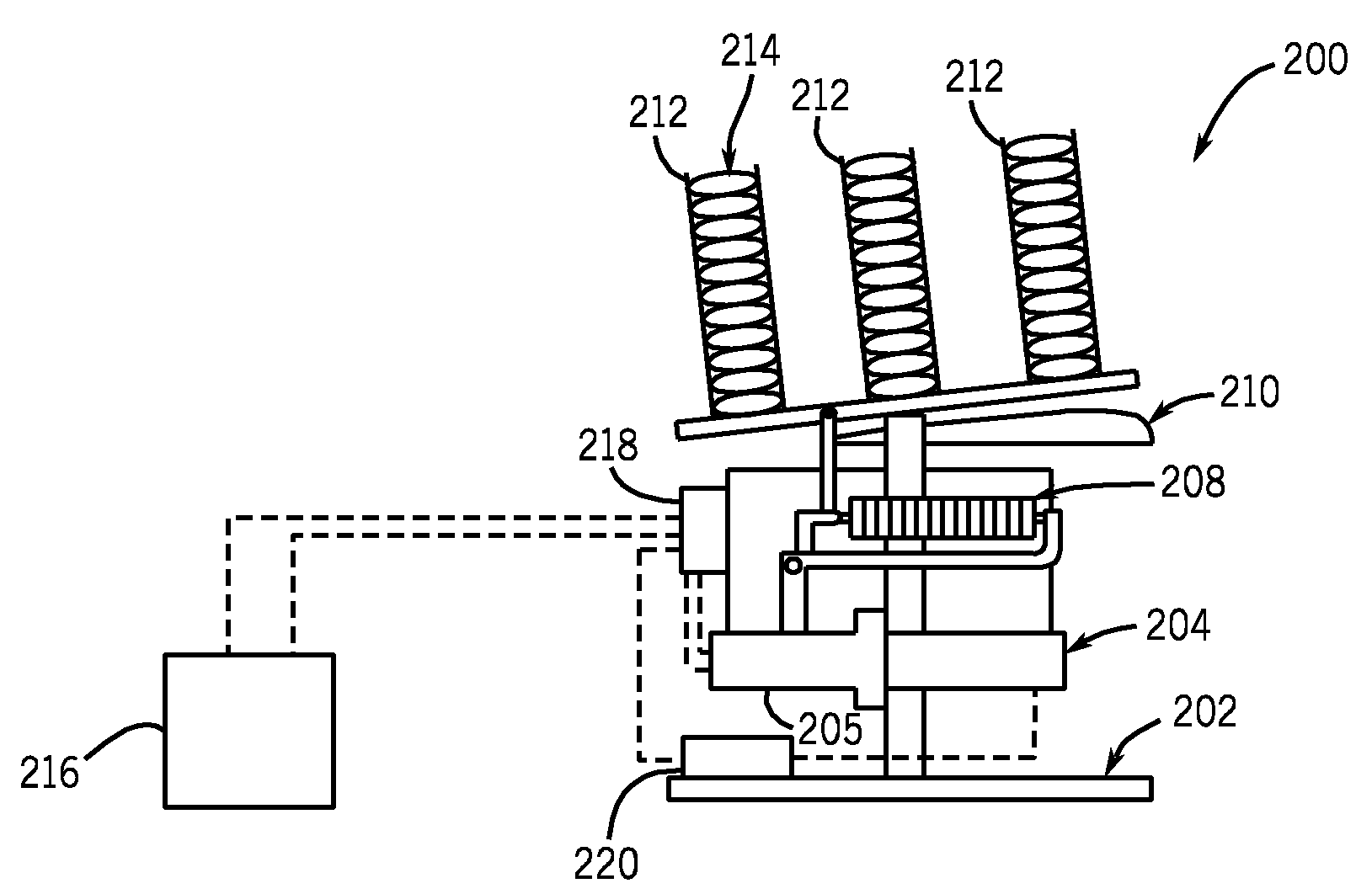
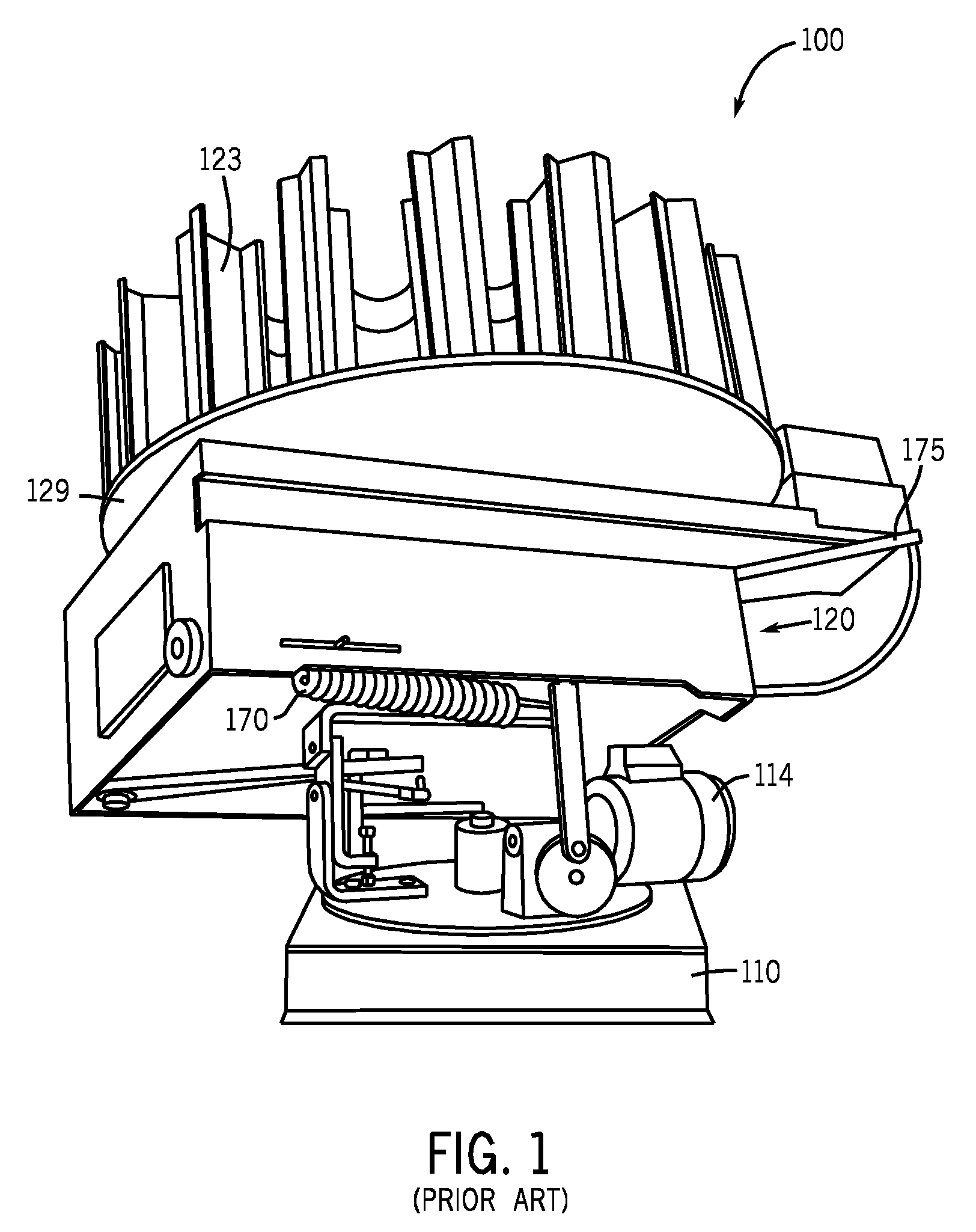
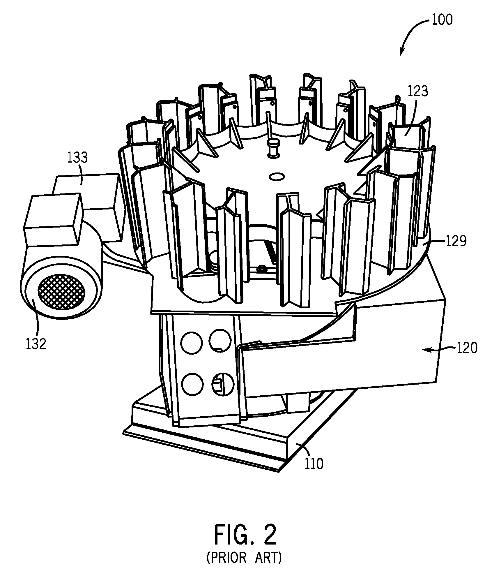
[0019]FIG. 3 illustrates a portable target throwing machine according to the present invention. In the embodiment of FIG. 3, a portable target throwing machine 200 comprises many of the same components as the conventional portable target throwing machine set forth in FIGS. 1 and 2. That is, portable target throwing machine 200 comprises a base 202, wherein base 202 is configured to be rigidly mounted to, for example, a wheeled cart (not shown). Such a configuration enables optimal portability of the system and allows the portable target throwing machine 200 to be placed in any suitable area chosen by a user. Further, motor 204 and gear box 205 are operable to energize a throwing spring 208 such that throwing spring 208 provides a biasing force on throwing arm 210. When a user provides a trigger signal through either a physical or voice activated switch (not shown), the force on throwing spring 208 is released and throwing arm 210 is quickly rotated so as to propel at least one clay ...


PUM


Abstract

A circuit module for preventing component failure in portable target throwing machines, the circuit module comprising a microcontroller coupled to a power source and a motor, wherein the microcontroller is configured to count a number of clay target throwing cycles and a run time of the motor. The circuit module also comprises a relay coupled to the microcontroller and the motor, wherein the relay is configured to open and interrupt power supply to the motor when at least one of the number of clay target throwing cycles and the run time of the motor exceeds a predetermined threshold.

Description

BACKGROUND OF THE INVENTION[0001]The present invention relates generally to portable target throwing machines for propelling clay targets, commonly referred to as trap or skeet machines, and is more specifically directed to the prevention of repeated target discharge when a component fails within the portable target throwing machine.[0002]Target throwing machines used for throwing clay targets during shooting practices and competitions are available in a wide variety of designs having varying complexities. Conventional target throwing machines generally include a frame portion having a planar throwing table on which clay targets may be positioned. A spring biased throwing arm may be turned about a vertical axle by a motor such that the arm is in contact with at least one clay target while the spring is loaded. When the clay target is to be discharged, the arm is released and permitted to rotate quickly about the axle due to the loaded spring. In this way, the clay target is propelle...

Claims


Application Information

Patent Timeline
IPC IPC(8): F41J9/18
CPCF41J9/30F41A19/01
Inventor SKELL, DANIEL G.KRUSCHKA, FREDERICKTAGLIAPIETRA, THOMAS D.MUNSALL, BRENT
Owner ELECTRO PRO
Why Eureka
Try Eureka