Attachment pylon for aircraft having a rear engine attachment beam offset from the caisson

a technology of rear engine and attachment beam, which is applied in the direction of aircraft power plants, power plant construction, power plant types, etc., can solve the problems of increased aerodynamic perturbation, aircraft performance loss, and inability to keep a flat lower face, and achieve the effect of reducing the geometry of the latter and increasing the mass of the assembly

Active Publication Date: 2010-05-27
AIRBUS OPERATIONS (SAS)
View PDF55 Cites 27 Cited by
  • Summary
  • Abstract
  • Description
  • Claims
  • Application Information

AI Technical Summary

Benefits of technology

[0018]Adding this intermediate piece relative to the embodiments of the prior art offers countless advantages, including that of moving this same caisson away from the engine suspended on the pylon. Consequently, the thermal conditions undergone by this caisson are less substantial than those found previously in embodiments where the fixing interface of the rear engine attachment, provided on its beam, was located directly on the lower longeron. This easing of thermal conditions therefore enables the use of materials less sensitive to heat to produce the rigid caisson, such as composite materials comprising a mix of resin and glass and / or carbon fibres. In such a case, a considerable gain in mass for assembly of the attachment pylon can be derived advantageously.

Problems solved by technology

This configuration causes various drawbacks, including that associated with directly connecting the beam of the rear engine attachment to the lower longeron.
Now, this configuration causes the lower part of the caisson to constitute a considerable obstacle in the flow zone of the secondary flow, and therefore cause elevated aerodynamic perturbation, due in particular to the substantial width of the essentially sized caisson as a function of the wing interface it supports.
The substantial aerodynamic perturbation encountered to the right of the rear engine attachment causes drag, resulting in performance losses of the aircraft.
Also, the fact of having to bring the caisson close to the engine casing usually requires modification of the geometry of this same caisson which is no longer capable of keeping a flat lower face.
This is inevitably translated by production constraints due to the complex assembly process of designing the lower part of the caisson, and by penalising oversizing of the attachment pylon in terms of overall mass.

Method used


Image

  • Attachment pylon for aircraft having a rear engine attachment beam offset from the caisson
  • Attachment pylon for aircraft having a rear engine attachment beam offset from the caisson
  • Attachment pylon for aircraft having a rear engine attachment beam offset from the caisson

Examples


Embodiment Construction

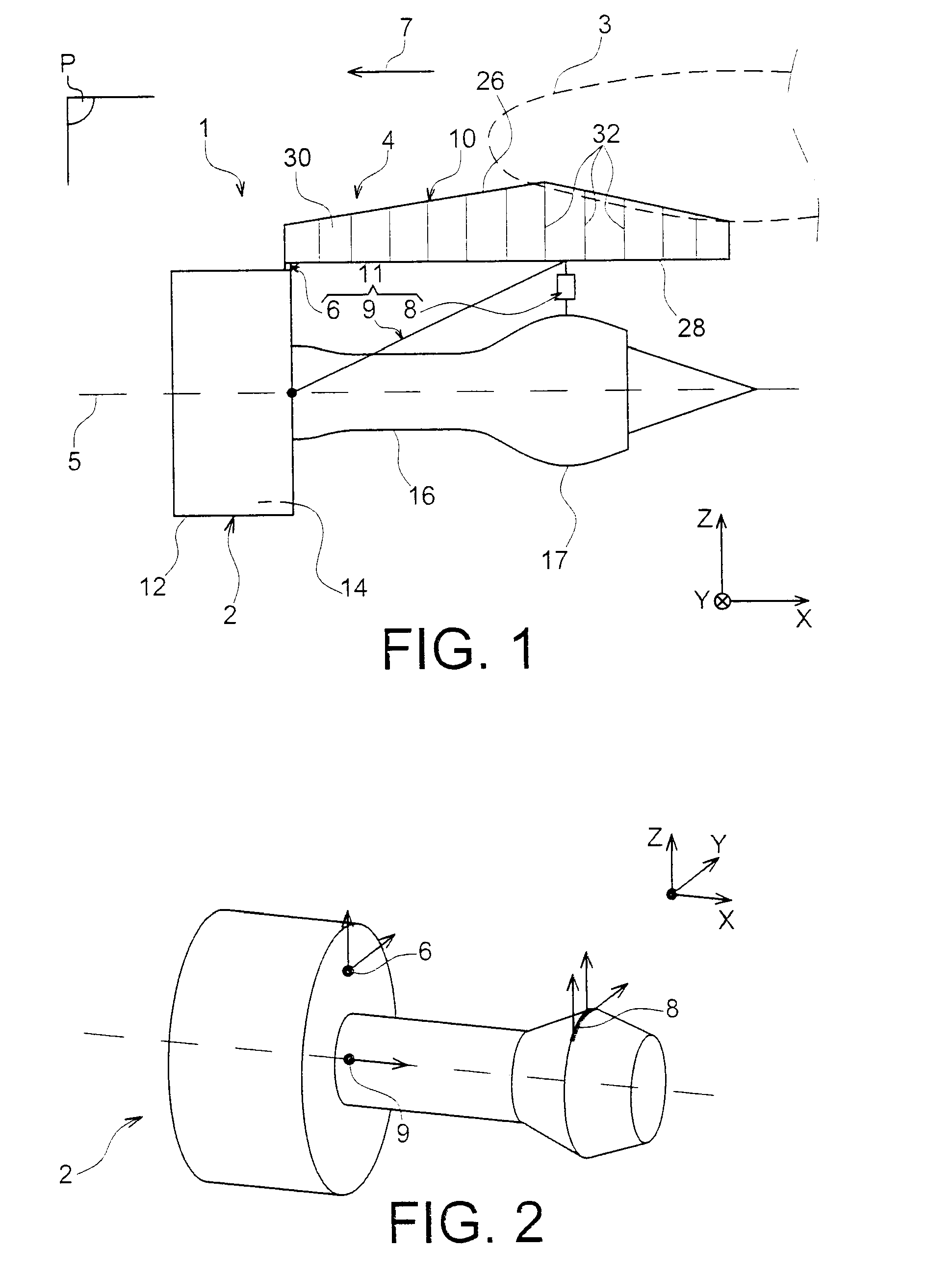
[0044]In reference to FIG. 1, this shows an aircraft engine assembly 1 to be fixed under a wing 3 of this aircraft, this assembly 1 forming an object of the present invention being provided with an attachment pylon 4 in the form of a preferred embodiment of the present invention.

[0045]Overall, the engine assembly 1 comprises an engine such as a turbojet engine 2 and the attachment pylon 4, the latter being especially fitted with a rigid structure 10 and an engine-mounting system 11 composed of a plurality of engine attachments 6, 8 and a thrust force collection device 9 generated by the turbojet engine 2, the assembly system 11 therefore being interposed between the engine and the abovementioned rigid structure 10, the latter also being called a primary structure. By way of indication, it is noted that the assembly 1 is intended to be enclosed by a nacelle (not shown in this figure), and that the attachment pylon 4 comprises another series of attachments (not shown) ensuring suspens...


PUM


Abstract

An engine attachment pylon for an aircraft including an intermediate piece interposed between a crossbar support and a rigid caisson, a first shear slug passing through a first interface fixing plane between the piece and the caisson, and a second shear slug passing through a second interface fixing plane between the piece and the support. Also, in side elevation, the intersection point between an axis of the pin and the plane, as well as the intersection point between an axis of the pin and the plane, are located on the common axis of two lateral thrust force collection connecting rods articulated on the crossbar.

Description

TECHNICAL FIELD[0001]The present invention relates in general to an aircraft engine assembly, of the type comprising an engine, an attachment pylon, and an engine-mounting system provided with a plurality of engine attachments and being interposed between a rigid structure of the attachment pylon and the engine.[0002]The invention also relates to such an aircraft engine attachment pylon.[0003]The invention can be used on any type of aircraft equipped for example with turbojet engines or de turboprop engines.[0004]This type of attachment pylon, also known as “EMS” (“Engine Mounting Structure”), for example suspends a turboengine below the wing of the aircraft, or else mounts this turboengine above this same wing.PRIOR ART[0005]Such an attachment pylon is in fact provided to constitute the linkage interface between an engine such as a turbojet engine and a wing of the aircraft. It transmits to the structure of this aircraft the forces generated by its associated turbojet engine, and a...

Claims


Application Information

Patent Timeline
Patent Type & Authority Applications(United States)
IPC IPC(8): B64D27/02B64D27/26
CPCB64D27/26B64D2027/268
Inventor COMBES, STEPHANESAMMITO, LAURENTBERJOT, MICHAEL
Owner AIRBUS OPERATIONS (SAS)
Why Eureka
Try Eureka