Shaft sealing system, preferably for a hydrogen cooled generator

a technology for sealing systems and shafts, which is applied in the direction of engine seals, dynamo-electric machines, supports/enclosements/casings, etc., can solve problems such as damage to seal rings and shafts

Inactive Publication Date: 2010-05-27
ALSTOM TECH LTD
View PDF6 Cites 9 Cited by
  • Summary
  • Abstract
  • Description
  • Claims
  • Application Information

AI Technical Summary

Benefits of technology

[0004]An object of the present invention is therefore to provide an improved sealing arrangement which makes use of sealing oil which is located in the clearance between the shaft and seal rings.

Problems solved by technology

For reasons of safety it is typically also necessary to provide redundant means for supplying oil to the seal rings because loss of oil to them may cause extensive hydrogen leakage from the generator and damage not only to the seal rings and the shaft, but also be dangerous due to the explosive hydrogen gas leaving the generator space.

Method used


Image

  • Shaft sealing system, preferably for a hydrogen cooled generator
  • Shaft sealing system, preferably for a hydrogen cooled generator
  • Shaft sealing system, preferably for a hydrogen cooled generator

Examples


Embodiment Construction

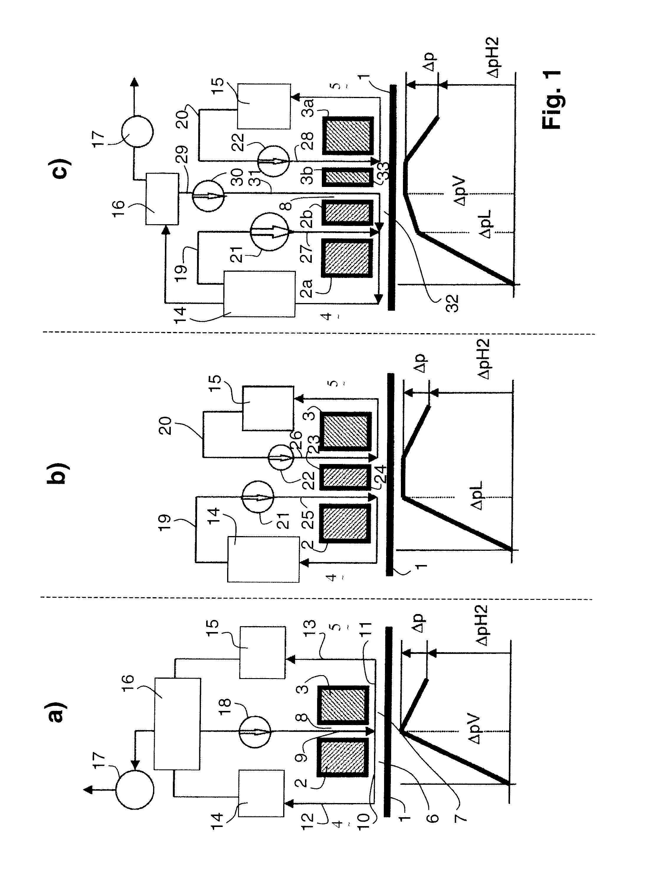
[0031]Referring to the drawings, which are for the purpose of illustrating the present preferred embodiments of the invention and not for the purpose of limiting the invention, FIG. 1 shows conventional sealing systems and shall be used to illustrate the general context of the present invention.

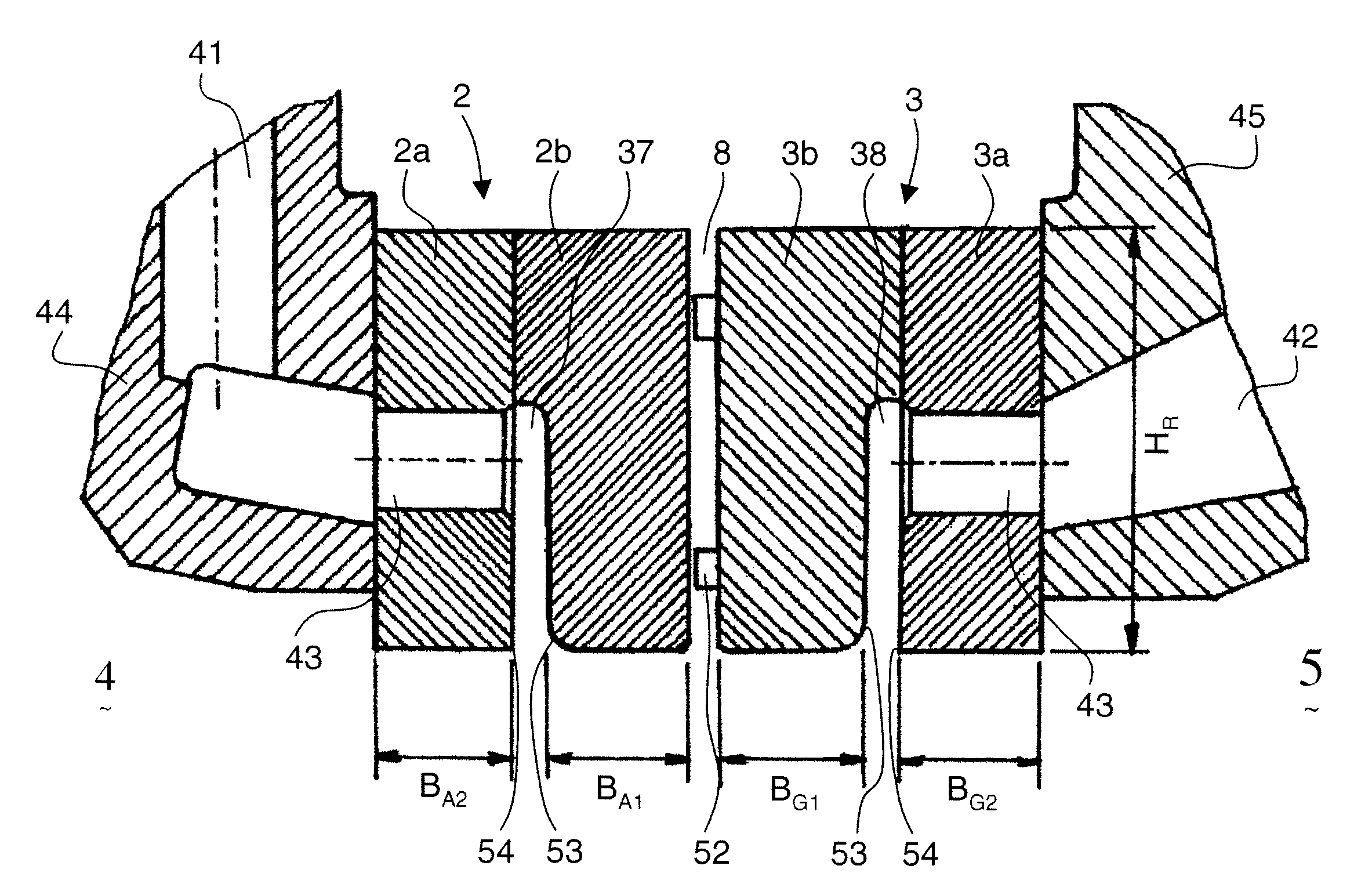
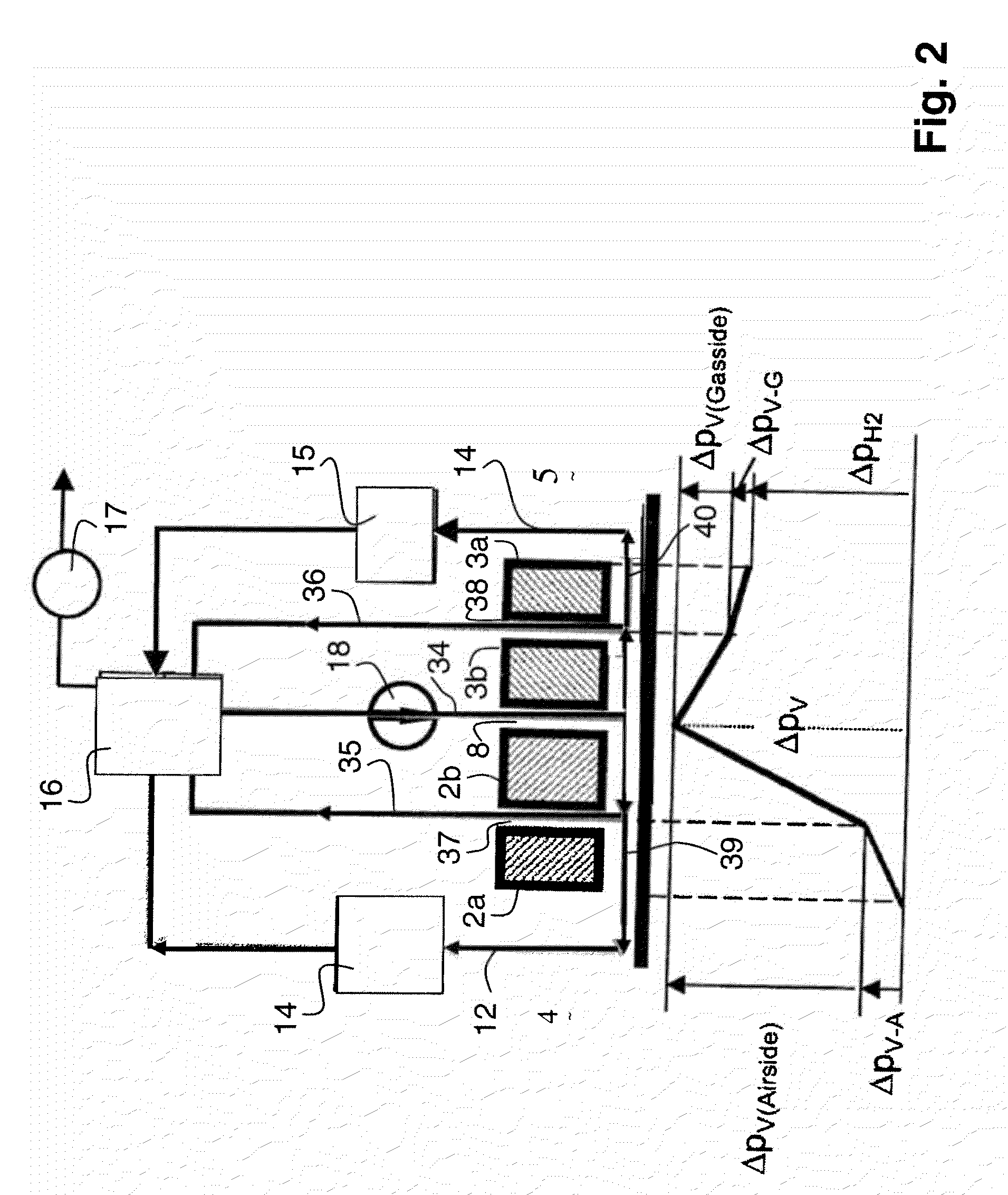
[0032]In FIG. 1a) a so-called single circuit sealing arrangement is displayed in a schematic view (axial cut in one radial section only). The shaft 1 is enclosed by two seal rings 2, 3. One of these seal rings is facing the air side 4, i.e. the outside of the generator housing, and the other seal ring 3 is facing the inner side of the generator, the so-called gas side 5 where the hydrogen gas is present for cooling of the hot parts of the generator.

[0033]Between these two rings 2, 3 there is a circumferential gap which forms the sealing oil supply channel through which a sealing oil flow 9 enters in a radial direction towards the shaft 1, and then due to the pressure which is higher than the ...


PUM


Abstract

A shaft sealing arrangement includes at least two seal rings radially enclosing a rotating shaft so as to define a clearance between the shaft and the at least two seal rings. A sealing oil supply channel is disposed between the at least two seal rings and a pump is configured for pumping a sealing oil through the sealing oil supply channel in a radial direction towards the shaft so that the sealing oil subsequently flows through the clearance in a first axial direction toward a first side of the sealing arrangement and in a second opposite axial direction toward a second side of the sealing arrangement. The sealing oil is collected on the first and second sides and at least partially reintroduced into the sealing oil supply channel. At least one seal ring includes a sealing oil return channel and at least a portion of the sealing oil flowing through the clearance exits the clearance in a radial direction through the sealing oil return channel and is at least partially collected and reintroduced into the sealing oil supply channel.

Description

TECHNICAL FIELD[0001]The present invention relates to the field of shaft sealing systems, preferably to generator shaft sealing arrangements. It specifically relates to such sealing arrangements which are based on sealing oil supply as they are used, for example, for hydrogen cooled turbo generators. It furthermore relates to uses of such sealing arrangements and methods for operating such sealing arrangements.BACKGROUND OF THE INVENTION[0002]In hydrogen cooled turbine generators the rotor shaft ends must be sealed by a gas side enclosure to prevent escape of the dangerous hydrogen gas along the shaft. To this end seal rings which are supplied with oil under pressure are used. Oil is pumped to a feed groove or sealing oil channel between the annular seal rings. When the oil pressure in the feed groove exceeds the gas pressure in the turbine generator, some oil is forced both ways in opposite directions along the shaft through the small clearance space between the seal rings and the ...

Claims


Application Information

Patent Timeline
Patent Type & Authority Applications(United States)
IPC IPC(8): F16J15/40
CPCH02K5/124F16J15/406
Inventor SCHUBERT, JOHANN
Owner ALSTOM TECH LTD
Why Eureka
Try Eureka