Faraday cage for camera

a faraday cage and camera technology, applied in the direction of coupling device connection, instruments, television systems, etc., can solve the problems of inability to use a faraday cage in full, limited effectiveness of this technique, and all electronic devices emit unwanted electrical signals, so as to reduce the transmission of unwanted radio frequency emissions

Active Publication Date: 2010-05-27
ROSEMOUNT AEROSPACE
View PDF16 Cites 38 Cited by
  • Summary
  • Abstract
  • Description
  • Claims
  • Application Information

AI Technical Summary

Benefits of technology

[0013]The passage through the Faraday cage can be dimensioned to reduce transmission of unwanted radio frequency emissions therethrough above a predetermined wavelength. The Faraday cage can be configured to attenuate emissions below 1 GHz by limiting gaps or openings within the Faraday cage to 1.5 cm or less.

Problems solved by technology

During operation, all electronic devices radiate unwanted electrical signals known as electromagnetic interference (EMI).
The effectiveness of this technique is necessarily limited by the need to use high frequency clocks and signaling.
In practical application, most electrical devices need a way to send signals in and out, such as by means of a cable, so a complete Faraday cage cannot be used.
This can be problematic for cameras used in EMI sensitive applications, such as onboard aircraft, for example.
Existing cameras have had difficulty passing the emissions and susceptibility requirements which are required for certification by the FAA or other governing authority.

Method used


Image

  • Faraday cage for camera
  • Faraday cage for camera
  • Faraday cage for camera

Examples


Embodiment Construction

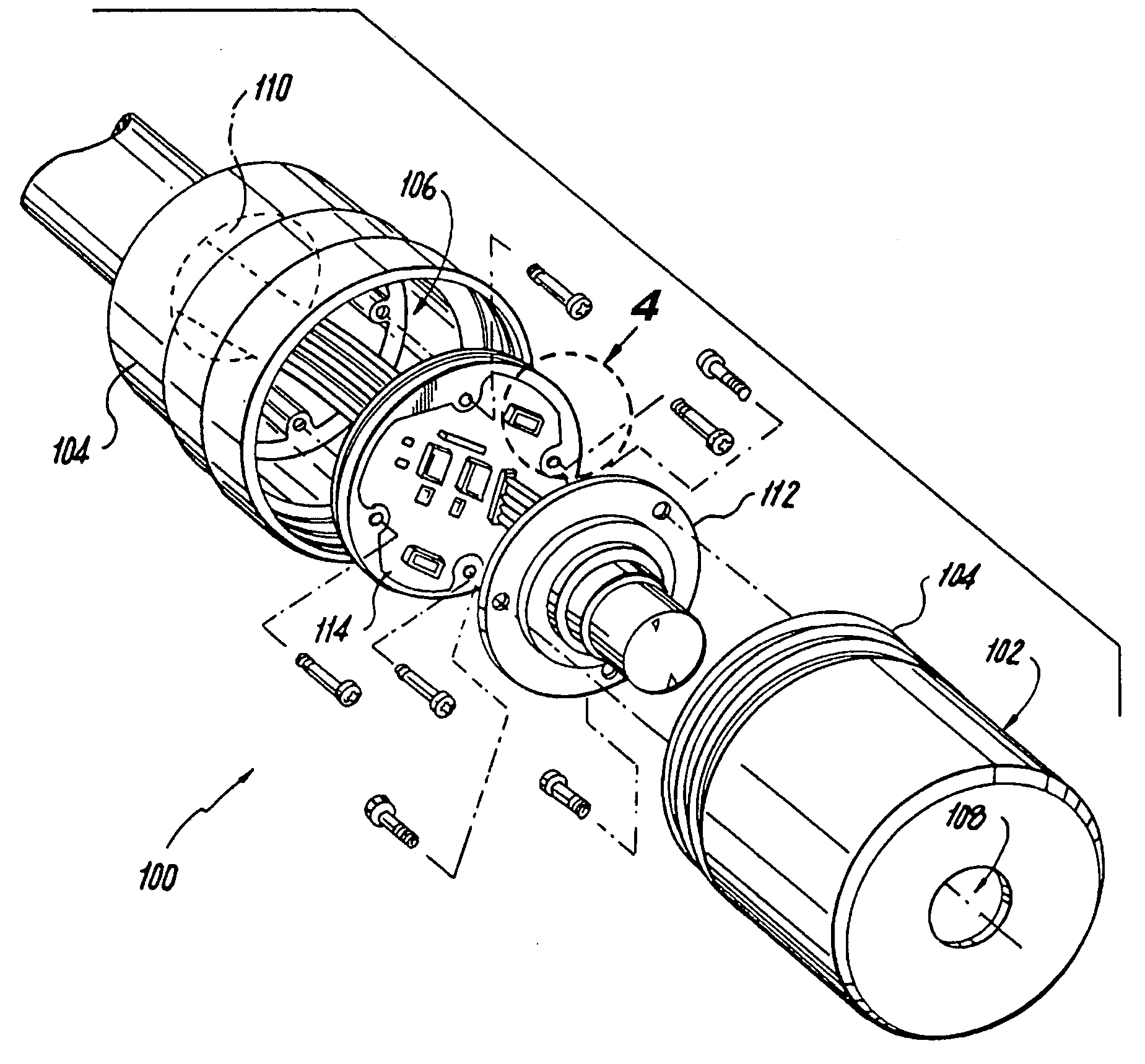
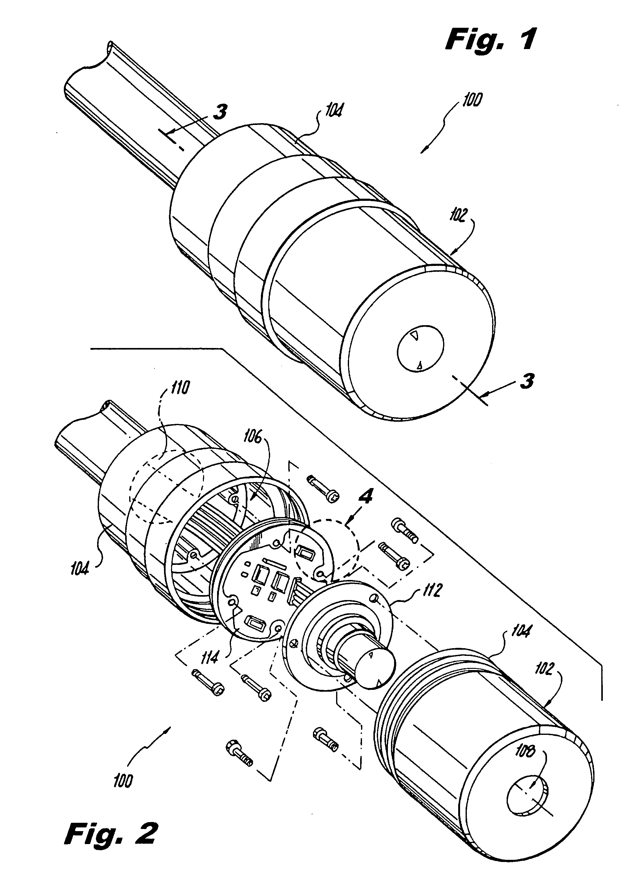
[0028]Reference will now be made to the drawings wherein like reference numerals identify similar structural features or aspects of the subject invention. For purposes of explanation and illustration, and not limitation, a partial view of an exemplary embodiment of a camera in accordance with the invention is shown in FIG. 1 and is designated generally by reference character 100. Other embodiments of cameras in accordance with the invention, or aspects thereof, are provided in FIGS. 2-10, as will be described. The devices and methods of the invention can be used to improve the EMI performance of cameras in EMI sensitive environments such as onboard aircraft, or in any other suitable application.

[0029]As shown in FIG. 1, camera 100 has an electrically conductive housing 102 defined by exterior walls 104 made of aluminum, or any other suitable material. FIG. 2 shows camera 100 in an exploded view to reveal interior cavity 106 within exterior walls 104. A lens opening 108 is provided t...


PUM


Abstract

A camera includes an electrically conductive housing defined by exterior walls and an interior cavity. The exterior walls of the housing have a lens opening and a connector opening formed therein. An imaging device is disposed within the interior cavity of the housing and communicates with the lens opening. A printed wiring board (PWB) is disposed within the interior cavity of the housing separating the imaging device from the connector opening. The PWB has an electrically conductive chassis plane operatively connected to the exterior walls of the housing so that the chassis plane and the housing form at least a partial Faraday cage around the imaging device.

Description

BACKGROUND OF THE INVENTION[0001]1. Field of the Invention[0002]The present invention relates to cameras and imaging devices, and more particularly to cameras for use in EMI sensitive environments.[0003]2. Description of Related Art[0004]During operation, all electronic devices radiate unwanted electrical signals known as electromagnetic interference (EMI). In general, unwanted EMI can be dealt with in two ways: either by electrical or circuit level modifications, or by physical shielding. Of course, a combination of both types can be used for a particular device as appropriate.[0005]Electrical techniques include modifying the timing of clock signals by frequency modulation so that the spectral density is reduced. This technique is also called clock skewing. This does not lessen the overall energy of the emitted EMI, but it does reduce unwanted peaks that would block frequency channels needed for data communication, e.g., by radio transmitters used in a mobile telephone. At the circ...

Claims


Application Information

Patent Timeline
Patent Type & Authority Applications(United States)
IPC IPC(8): H05K9/00G03B17/02
CPCH04N5/2252H04N23/51H05K1/02H05K9/0007
Inventor OPHOVEN, TIMOTHY M.HUSS, CHARLES G.BENNING, KEVIN J.EVANS, NATHAN D.
Owner ROSEMOUNT AEROSPACE
Why Eureka
Try Eureka