Method for estimating channel in radio communication system and device therefor

a radio communication system and channel estimation technology, applied in the field of radio communication devices, can solve the problems of high implementation complexity, processing delay time increase, and difficulty in employing the lmmse channel estimation scheme, and achieve the effect of enhancing the performance of the channel estimation unit and higher performan

Active Publication Date: 2010-05-27
RES & BUSINESS FOUND SUNGKYUNKWAN UNIV
View PDF7 Cites 29 Cited by
  • Summary
  • Abstract
  • Description
  • Claims
  • Application Information

AI Technical Summary

Benefits of technology

[0042]As described above, according to the channel estimation method in a radio communication system, provided by the present invention, it is possible to largely enhancing the performance of a channel estimation unit which can be used in the general radio channel environments.
[0043]That is, the present invention provides a method more suitable to the real channel environment, where error occurs due to dense delay positions of a multi-path channel, and a delay position not corresponding to integer times of a discrete sample space exists, thereby being able to provide a radio communication system having much higher performance.

Problems solved by technology

However, the LMMSE channel estimation scheme has disadvantages in that a large number of calculations are required to obtain the statistical characteristic of a channel, the implementation complexity is high, and a processing delay time increases.
That is, it is difficult to employ the LMMSE channel estimation scheme due to the burden of implementing a receiver.
However, such complexity reduction schemes cause serious estimation error when they are employed in an actual radio channel environment.
A representative cause of estimation error is a dense multipath channel environment, and a general radio channel environment, where it cannot be guaranteed that the length of a transmission delay is modeled by integer times of a sample space, may be regarded as a cause of error in channel estimation.
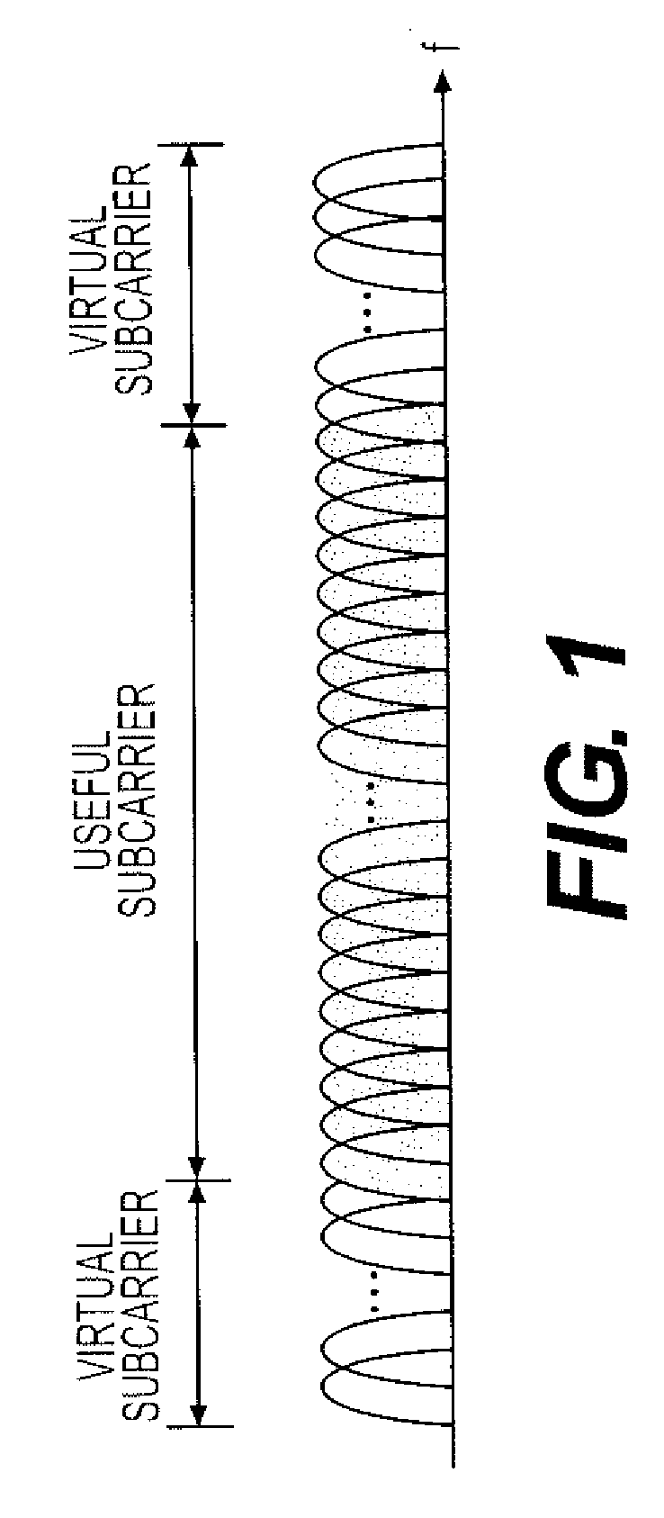
Meanwhile, such a setting of a guard band makes it difficult to implement a channel estimator based on time-domain channel impulse response (CIR) estimation.
Such a noise removal scheme intends to enhance the channel estimation performance, but may degrade rather than enhance the performance due to a wrong operation of removing even useful channel components in a noise removal procedure in the OFDM system, where a guard band has been set.
First, when delay positions of a channel aggregate densely, new error is caused by interference between CIR values of corresponding positions. In this case, when a scheme of removing errors one by one from the channel's position having the highest power, like the conventional method, is used, it is impossible to remove the error caused by the interference. Also, since the employed non-ideal autocorrelation function is set based on integer times sample spaces, the error compensation scheme cannot be successfully performed if the delay positions of the channel do not correspond to integer times of the sample space.
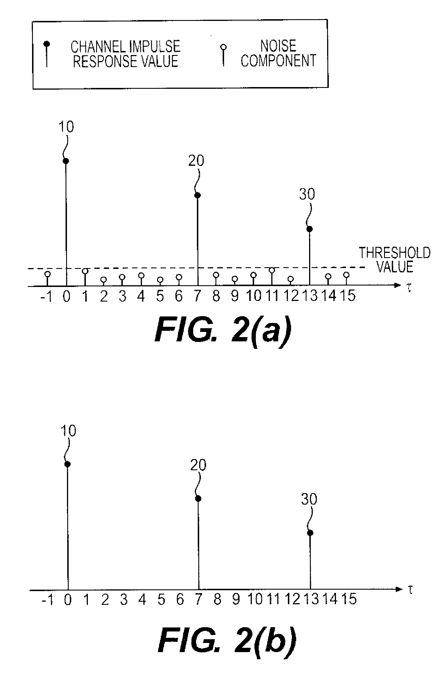
Also, random noise is distributed in discrete sample positions along a delay time axis.
However, FIGS. 2A and 2B are only ideal estimation examples, but in reality, such a result is not obtained due to a guard band and a non-sample-spaced channel delay position.
That is, a phenomenon where impulse responses are not in a precisely separated form, but is dispersed to both sides, thereby causing power loss, is caused.
on. Accordingly, when the CEC scheme is performed based on a CIR value including initial error, channel components existing at both sides are not sufficiently removed. FIG. 4C shows a result of a wrong operation caused by the
CEC. Consequently, the channel components remaining around Numbers 10 and 20 cause new channel
Therefore, when the conventional channel estimation error compensation scheme is applied in a general wireless channel environment, where it cannot be guaranteed that the length of a transmission delay is modeled by integer times of a sample space, the reception performance is degraded.

Method used


Image

  • Method for estimating channel in radio communication system and device therefor
  • Method for estimating channel in radio communication system and device therefor
  • Method for estimating channel in radio communication system and device therefor

Examples


Embodiment Construction

[0055]Hereinafter, an exemplary embodiment of the present invention will be described in more detail with reference to the accompanying drawings.

[0056]FIG. 6 is a block diagram illustrating the operation procedure of a channel estimation error compensation method according to an exemplary embodiment of the present invention.

[0057]A signal received by a receiving-side antenna is transformed into a baseband discrete signal through an RF unit 100. On the assumption that time and frequency synchronizations have been sufficiently achieved, in the next step, a guard interval removal unit 110 removes a guard interval in an OFDM symbol.

[0058]In the next step, a serial / parallel conversion unit 120 converts a signal stream input in serial into parallel signals. The parallel signals are simultaneously input to a first Fast Fourier Transform unit 130, and is subjected to a Fourier transformation. In this case, the signal is transformed from a time domain to a frequency domain. A part of the out...


PUM


Abstract

Disclosed is a radio communication device, and more particularly to a method for estimating a channel and compensating for error occurring in the estimation procedure, for a device for performing a frequency domain signal processing, such as Orthogonal Frequency Division Multiplexing (OFDM) The channel estimation method in a radio communication system includes the steps of: transforming a received OFDM signal into a frequency domain; estimating a channel frequency response (CFR) value from a result value obtained through the transformation by using a pilot signal; transforming the estimated CFR value into a time domain through an extended Inverse Fast Fourier Transform scheme, and detecting a channel impulse response (CIR) value; detecting a delay path position of a channel; modifying a non-ideal autocorrelation function; and compensating the estimated CIR value for error, through use of the detected delay path position and the non-ideal autocorrelation function.

Description

BACKGROUND OF THE INVENTION[0001]1. Field of the Invention[0002]The present invention relates to a radio communication device, and more particularly to a method for estimating a channel and compensating for error occurring in an estimation procedure in a system where a frequency domain signal processing, such as Orthogonal Frequency Division Multiplexing (OFDM), is performed.[0003]2. Description of the Prior Art[0004]In radio communication environments, received signals have a frequency-selective power spectrum characteristic due to transmission delay caused by a multipath. In order to compensate for such a distortion on channels, various channel estimation schemes have been studied.[0005]Among channels estimation schemes, a Linear Mean Square Error (LMMSE) channel estimation scheme has been widely known as a scheme of minimizing estimation error caused by noise. However, the LMMSE channel estimation scheme has disadvantages in that a large number of calculations are required to obt...

Claims


Application Information

Patent Timeline
Patent Type & Authority Applications(United States)
IPC IPC(8): H04L27/28
CPCH04L25/0208H04L25/0212H04L25/022H04L2025/03611H04L25/03159H04L2025/03414H04L25/0224H04L25/0204H04J11/00
Inventor HYUNG-JIN, CHOISE-BIN, IM
Owner RES & BUSINESS FOUND SUNGKYUNKWAN UNIV
Why Eureka
Try Eureka