
Image coding method and image decoding method

a coding method and image technology, applied in the field of image coding methods, can solve the problems of large amount of data to be sent, and achieve the effects of accurate prediction, reduced coded distortion, and higher coding efficiency

Active Publication Date: 2010-05-27
SUN PATENT TRUST
View PDF19 Cites 166 Cited by
  • Summary
  • Abstract
  • Description
  • Claims
  • Application Information

AI Technical Summary

Benefits of technology

"The present invention provides an improved method and apparatus for coding and decoding image data and video data. The method uses a larger number of prediction directions, resulting in higher coding efficiency and reduced coded distortion. This is achieved by dividing video frames into blocks of pixels and predicting each block using a different direction. The method also allows for better prediction of sharp linear edges in video data. Overall, the invention provides a more effective and efficient way to compress and transmit video data."

Problems solved by technology

When video data is being transmitted or recorded, a substantial amount of data has to be sent through conventional transmission channels of limited bandwidth or has to be stored on conventional storage media of limited data capacity.

Method used


Image

  • Image coding method and image decoding method
  • Image coding method and image decoding method
  • Image coding method and image decoding method

Examples


Embodiment Construction

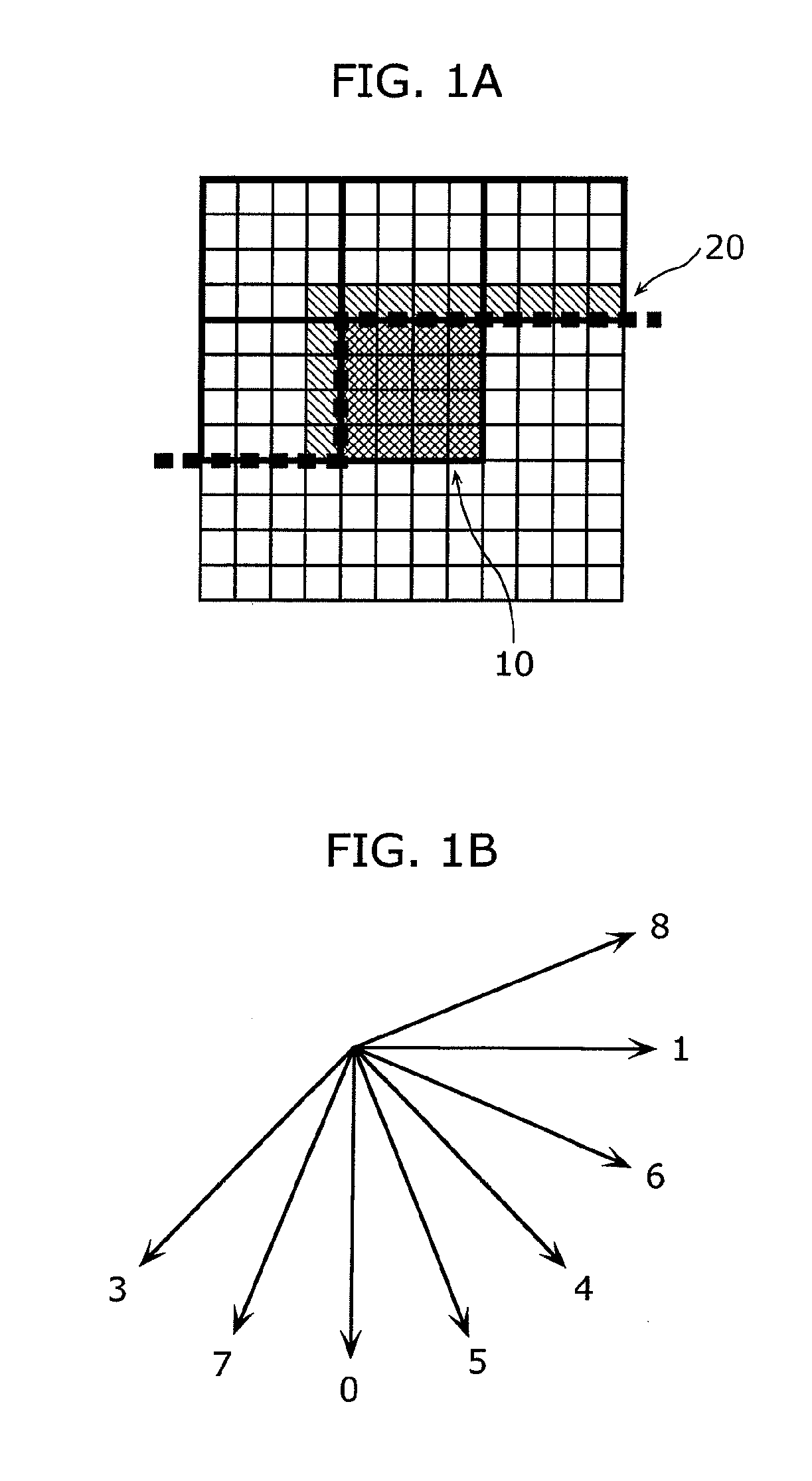
[0116]The image coding apparatus and image decoding apparatus according to an embodiment can detect an edge included in surrounding blocks of the current block, and allow the use of an edge prediction mode in which a direction of the detected edge is used as an intra-prediction direction. In other words, the embodiment makes it possible to perform intra-prediction coding on a picture including a sharp edge by taking the direction of the detected edge into accounts.

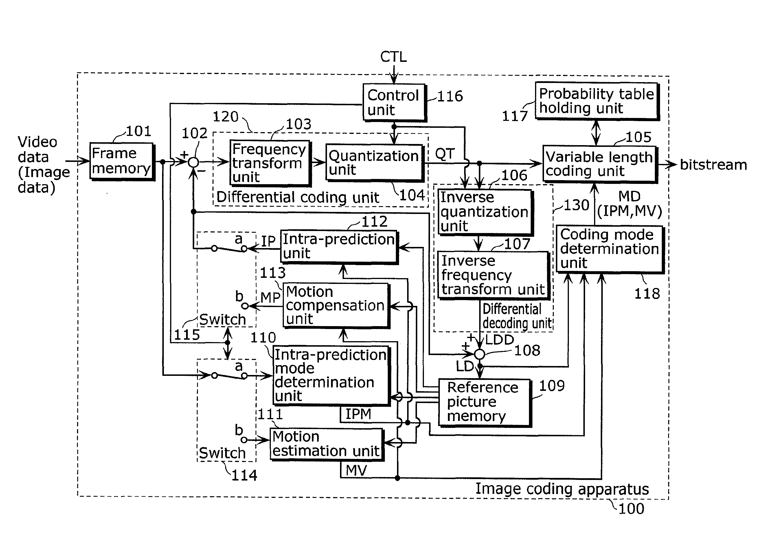
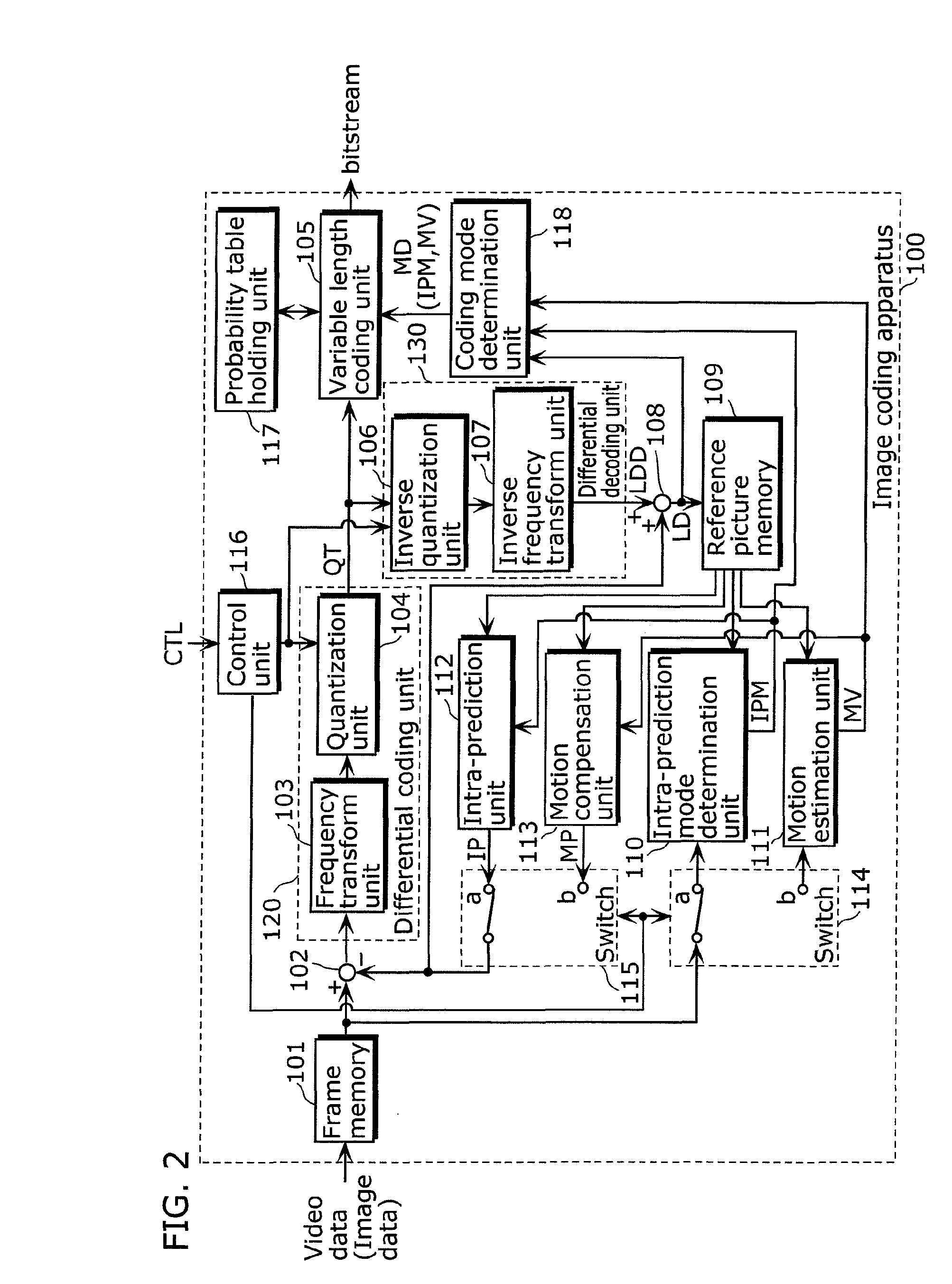
[0117]FIG. 2 is a block diagram illustrating an example of a configuration of an image coding apparatus 100 for hybrid video coding according to the embodiment. The image coding apparatus 100 includes a frame memory 101, a subtracting unit 102, a frequency transform unit 103, a quantization unit 104, a variable length coding unit 105, an inverse quantization unit 106, an inverse frequency transform unit 107, an adding unit 108, a reference picture memory 109, an intra-prediction mode determination unit 110, a motion estima...


PUM


Abstract

Provided is an image coding method for performing intra prediction achieving higher coding efficiency. The method for coding image data on a block-by-block basis includes: generating a predicted block by predicting a current block; computing a difference between the current block and the predicted block; coding the difference computed in the computing; decoding the difference coded in the coding; and adding the difference decoded in the decoding to the predicted block to generate a decoded block, wherein the generating includes: detecting an edge in a previously decoded block corresponding to a block adjacent to the current block; and extrapolating or interpolating previously decoded image data corresponding to a pixel included in the block adjacent to the current block, along a direction of the edge detected in the detecting to generate the predicted block.

Description

TECHNICAL FIELD[0001]The present invention relates to an image coding method for compression-coding image data and video data with improved coding efficiency, an image decoding method for reconstructing the image data and video data that have been compression-coded, and a corresponding image coding apparatus and image decoding apparatus.BACKGROUND ART[0002]An ever increasing number of applications for video-conferencing, digital video broadcasting, and streaming of video contents over the Internet such as for video-on-demand services relies on a transmission of video information. When video data is being transmitted or recorded, a substantial amount of data has to be sent through conventional transmission channels of limited bandwidth or has to be stored on conventional storage media of limited data capacity. In order to transmit video information through conventional channels and store it on storage media, it is inevitable to compress or reduce the volume of digital data.[0003]For ...

Claims


Application Information

Patent Timeline
Patent Type & Authority Applications(United States)
IPC IPC(8): G06K9/36H04N19/593
CPCH04N19/00733H04N19/176H04N19/14H04N19/593H04N19/11H04N19/51H04N19/119
Inventor DRUGEON, VIRGINIEWEDI, THOMASPALFNER, TORSTENSASAI, HISAO
Owner SUN PATENT TRUST
Learn More